The Origins of the Mono-Tube Boiler
Accounts of early Mono-tube Boilers seem to start with Jacob Perkins who was born in 1766. The Baker Perkins Historical Society (2020) report that the Perkins family were a US/UK dynasty with similar, but wider, industrial interests to the later Herreshoffs. One obsession of Jacob Perkins (and later of his grandson Loftus), was the use of high-pressure steam and the Uniflow engine which he had patented in 1827 (See Fig 1).
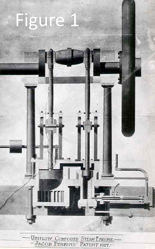
The generator, as he called the boiler, was the crucial part of his engine. A cylinder of 3-inch thick gunmetal, closed at both ends, was fixed in the furnace so that the fire played all around it. Operated by the engine itself, bellows boosted up the heat of the fire until the generator reached a temperature of 450 degrees F., and the super heated water was forced into a pipe, where it flashed into high-pressure steam and exploded at 500 pounds to the square inch into the working cylinder. At 200 strokes a minute, the engine was reckoned to develop 10-horse power. To keep the pipe joints steam tight, Perkins invented the double-cone pipe joint.
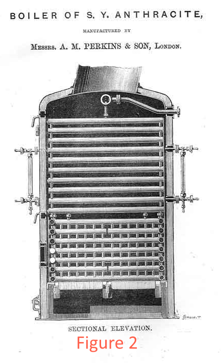
Other accounts describe a matrix of cast iron square section tubes joined outside the fire. Later, the Perkins boilers used the same form of horizontal straight tube matrix but now with vertical link tubes and water gauges (See Fig 2). Clearly this design is not a mono tube as currently understood but is a very different technology to fire tube boilers which were widely used at the time.
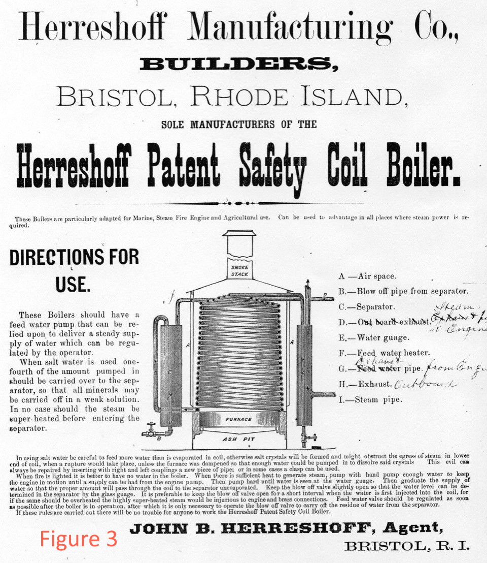
By the 1870’s the Herreshoff type of coil boiler became popular, as a result largely of steam boat boiler explosions on the US rivers. The first advertisement for these from 1873 is shown in Fig 3. Note that this is in the name of the blind John B Herreshoff (1841-1915) and not Nat Herreshoff (1848-1938) the boat designer. To compound matters, James Herreshoff (1834-1930) is named in the boiler Patent. He was a well known chemist.
The iron tubing of that period still had to be hammer welded into a continuous coil, and that seems to have been the weakness of the design. So much so that in 1885 Herreshoff changed to using a square pattern boiler with screwed joints and straight tubes. However, over ten years they built no less than 86 boats using the earlier coil boiler, not counting those boilers that were built under licence. Clearly the boiler was not the failure it is sometimes painted.
Practical Small Mono-tube boilers for launches
The scaling down (or up) of any successful boiler is difficult. Areas change as the square of the linear scale, and volumes (and hence weights) as the cube. The smaller the boiler the shorter the time constants will be, leading to unstable steam delivery and fussy” firing demands.
There are fixed size limitations too, as the minimum fire door size in launch applications is about 125mm x 100 mm and, with solid fuels, space for stoking must be provided around the boiler to allow human size firing tools to be used. This is a particular problem in small canoes or launches where the user has to reach over the engine in order to fire, as well as needing visibility into the fire bed.
For an example, consider the Herreshoff Torpedo Boats that were supplied to the British Admiralty in 1878 whose performance was reported on by Maw (1888). Those boats had coil boilers that were 56 inches outside diameter by 65 inches height to the funnel base, and had 12.5 square feet of grate. The heating surface consisted entirely of 300 feet of lap welded wrought iron pipe of about 2 inches diameter in a double beehive coil. Boiler weight was two tonnes, and under fairly forced conditions, the compound engine could produce 150SHP at 150psig, burning 600 lb of coal per hour.
For launch use, working on a nominal ¼ scale version of that specification, it might be expected to get nearly down to the scale weight of 60 lbs (27 kg) using thin modern materials such as stainless steel. That would also provide around 10 square feet (0.9 sq M) of heating surface and a one shaft horsepower (0.75 kW) engine would seem to be a fair design target. Proportionately that would be burning up to 8lb (4 kg) of solid fuel per hour.
Separator
The Herreshoff Patent importantly realised that the stable way to operate the boiler was to use an excess of feed water, and separate the steam from the excess water externally. Notice that the drain valve is not at the bottom of the separator vessel in Fig 3, as that is where scale accumulates. Otherwise, a separator provides a convenient manifold for mounting all the boiler outlet fittings.
Feed
Yet again, on the subject of water feed, Herreshoff’s 1873 Patent was spot on in specifying that reliable and regulated feed water is needed. That effectively rules out main engine driven feed pumps. Ideally any solid fuel boiler installation should be able to operate continuously in a stand alone manner without recourse to engine pumps. With a conventional boiler an injector is all that might be required to fulfil this but with the continuous feed needed for a mono-tube, a reliable donkey pump would be required. Fortunately, a rough calculation of the power required to feed this one shaft horsepower boiler, shows that around one watt of mechanical effort is all that is needed. Thus a simple battery operated electric plunger pump should be sufficient. Alternatively, a Weir type donkey pump could be run off the drain valve line
Next: 1879 Steam Canoe Nina