1. Propellers and weed
For any small steam boat or steam canoe builder there will eventually be a time to address the issue of getting the propeller. Much effort can be expended in trying to find the optimum dimensions and the most enthusiastic builder will no doubt have begged or borrowed a copy of Gerr's Propeller Handbook. Unfortunately, as was shown in the Fairlight discussion of propeller options, Gerr does not offer a quick and simple answer. In part that is because the book is really aimed at the higher speed internal combustion engine driven propellers rather than the slower low power steam driven propellers.
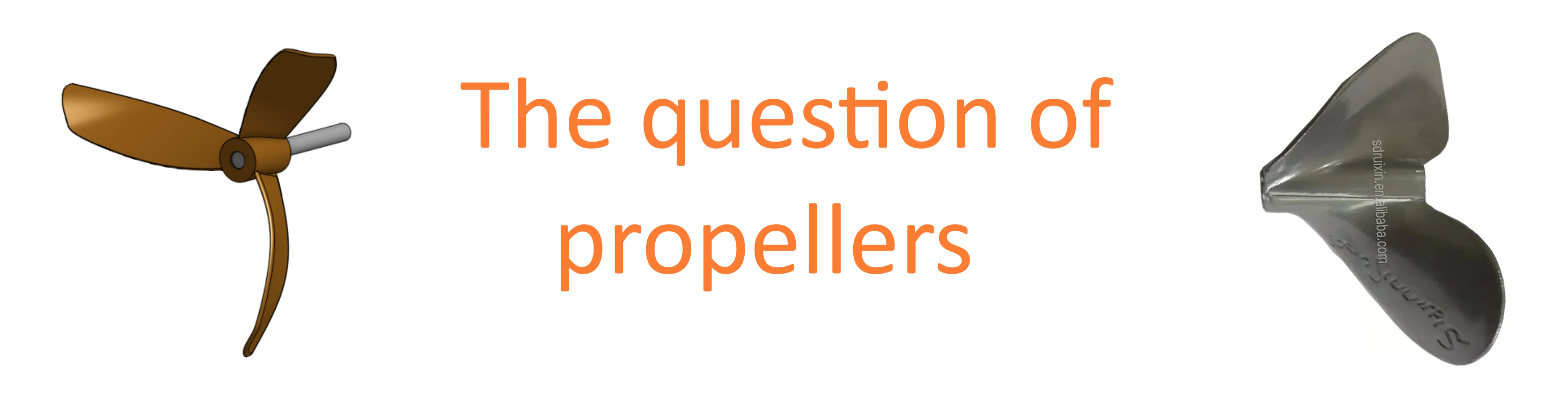
One ‘rule of thumb’ solution is to investigate what other people have used for similar sized and powered boats. This route rather assumes that those that got the solution wrong will have changed their propeller to something that works rather better. Thus with a rough idea of diameter and pitch the search is on to find one to buy. The internet is full of advertisements for propellers although most seem to be as replacements for outboards motors. There are some interesting objects to be found such as the propeller to the right in the heading picture that was found on the Alibaba site. Sadly, communication with the vendor did not yield diameter and pitch specifications or shipping to Europe costs.
There is also a tendency within the Steam Launch Community to favour ‘traditional’ propellers simply because they look so nice and, usually being made of bronze, will polish up to a beautiful shine. 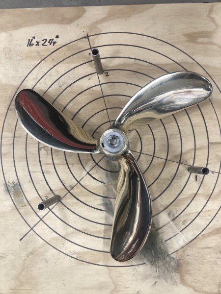 Sadly, original propellers of this style are fairly rare and the re-productions tend to be very expensive. Thus many in the Community resort to the solution of making their own propeller. There is a good piece on propeller making in Steam Boats and Modern Steam Launches by Weston Farmer (September-October 1962, Page 18). This will enable the would be designer to specify the diameter and pitch and then get the shape of the blade about correct. However, Weston Farmer’s suggested blades are very wide and quite unlike the traditional propeller.
Those who build their own propellers also tend to make use of straight material since it is economical and makes construction somewhat easier. A couple of good examples of beautifully made ‘straight’ propellers are to be seen on Reciproca 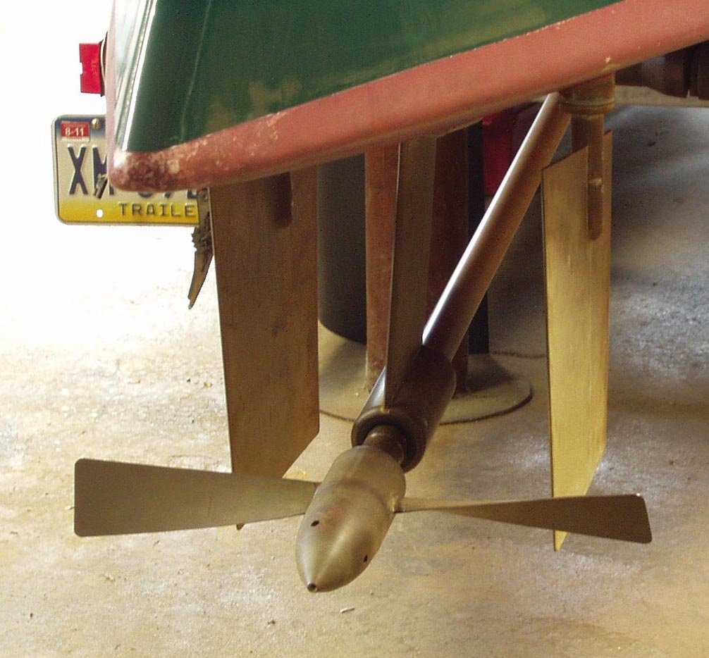 (below) and similarly on Snipe. These are reported to work very well in clear water but when there is weed and other debris they tend to become clogged very quickly.
If one looks at the traditional propeller design a key feature seems to be that the blades appear to slope backwards. To find why that is the case some extensive internet research only yielded the following “Curved propeller blades ... reduce drag at the tip of the airfoil where the blade speed is the highest. This increases the efficiency of the propeller” Given the likely date in which the traditional propeller was introduced one wonders if Victorian builders had discovered that or perhaps they had hit upon the other issue; that of weed clogging. Does the traditional propeller shed weed rather than collect it?
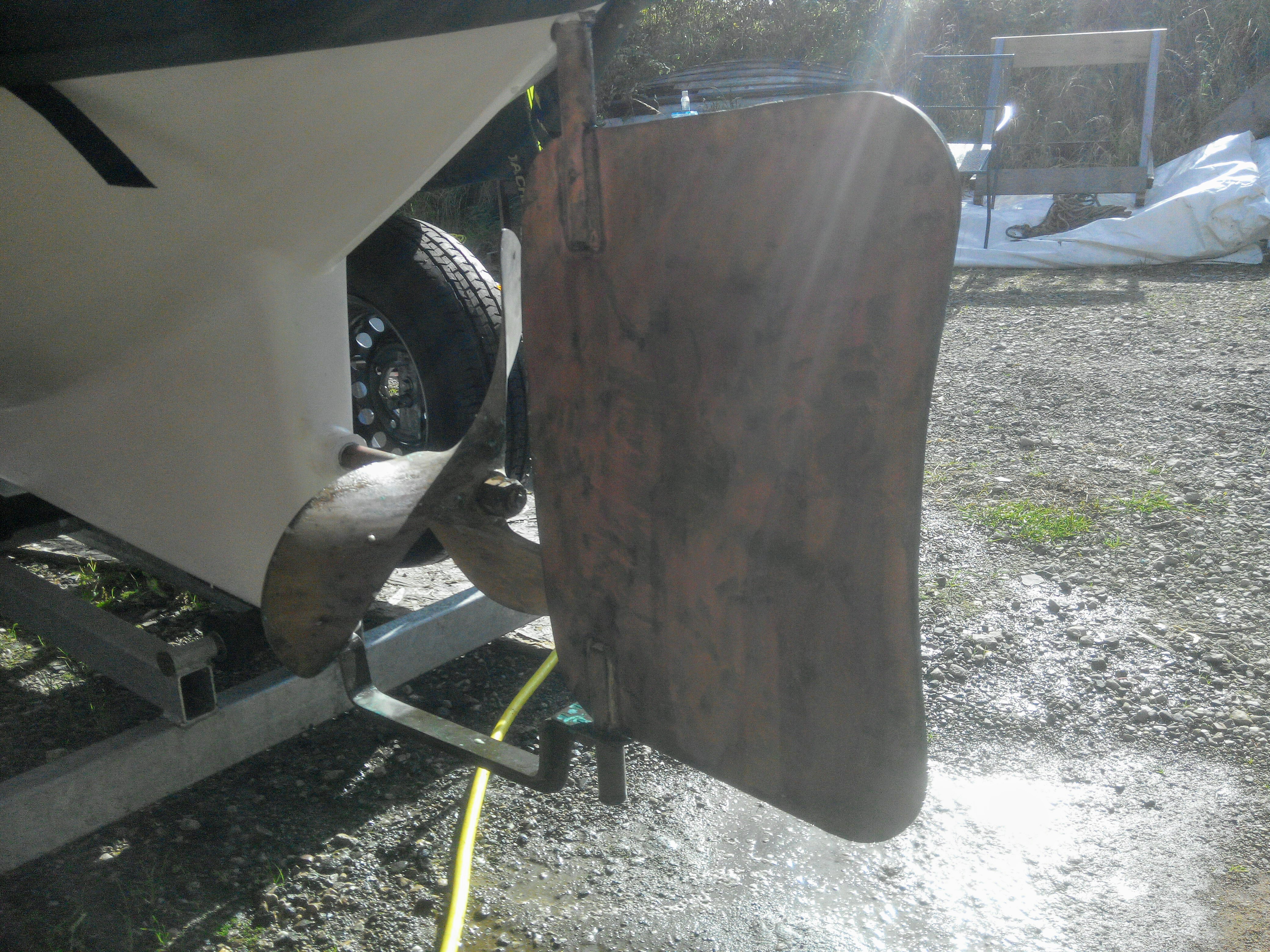
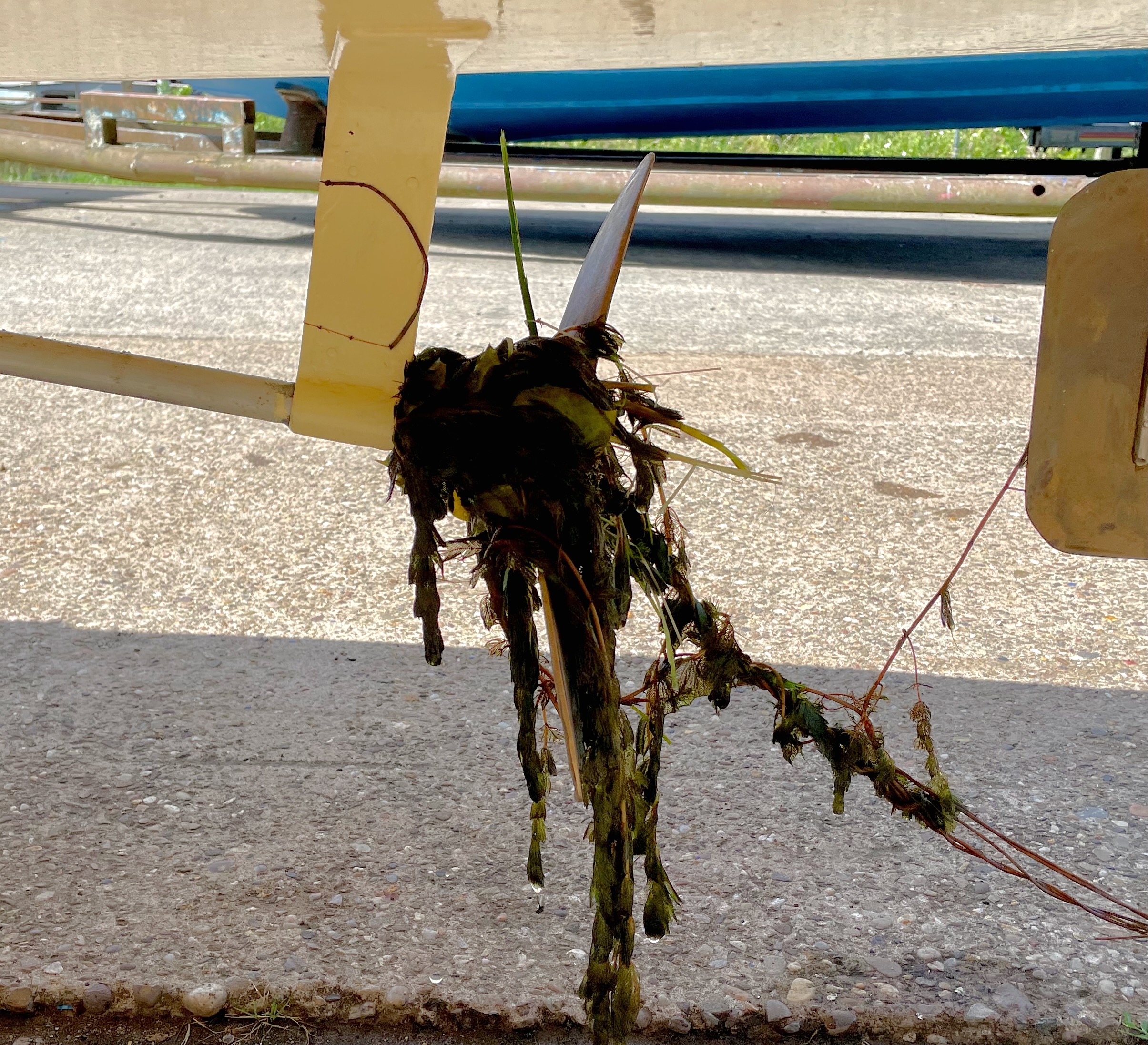 Few steam boat owners can claim that they run totally weed free, but as mentioned above the two blade prop on Snipe clearly doesn’t compare with the three bladed prop of the larger boat for which it was claimed that weed clogging had not been a problem
 .
.
One reason for this might lie in the off centre blade-to-root joint of the cleaner prop. This would produce a slicing rather than stirring action at the root, moving any potential weed knot up the blade, where the reducing curved section should throw the obstruction off.
In order to test this hypothesis, three 3mm brass blades were cut to the same shape as the traditional propeller. This was a trace of the traditional propeller blade pictured above. The blades were then twisted to create a spiral pitch and silver soldered to a triangular brass root. After smoothing the root and shaping the blades, a reasonable 12” x 12” prop was produced with the blades offset from centre by the triangle’s dimensions. Full details of the design are given in the section below; Building a Traditional 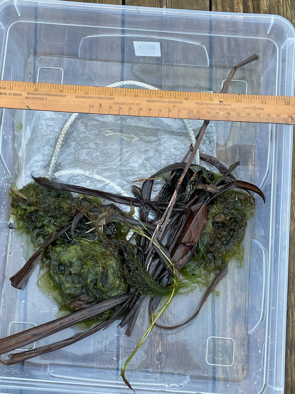 Style Propeller.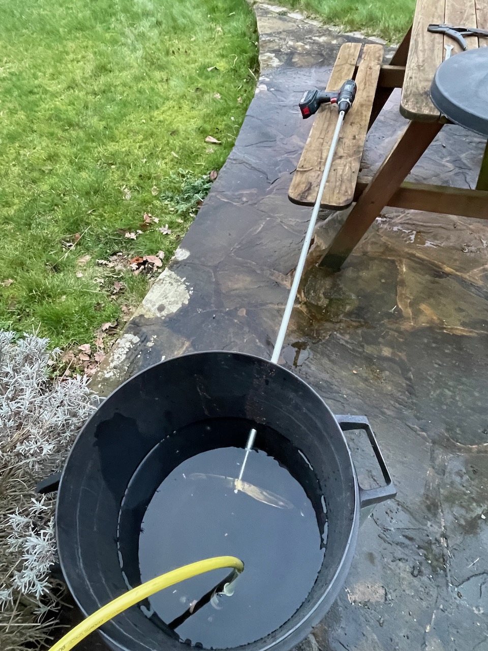
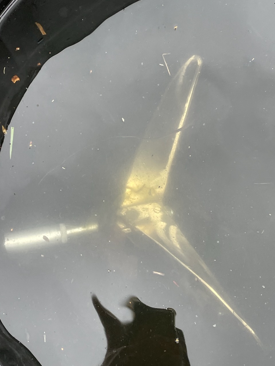
This propeller was compared under weeding conditions with the original two bladed prop from Snipe. To do this both props were run alternately below water level in a plastic dustbin.
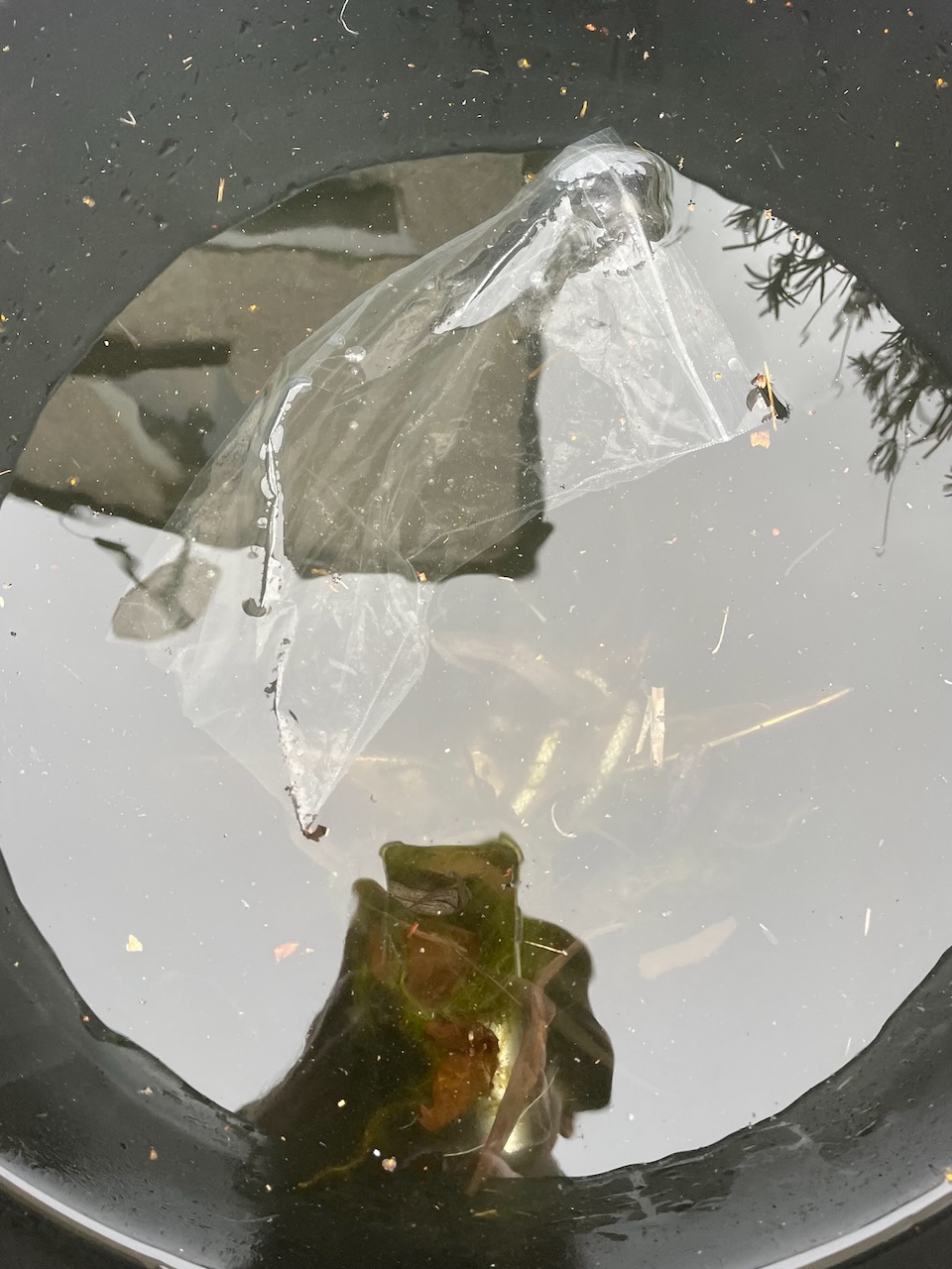
To the water there was added a quantity of pond weed, a piece of rope and the obligatory plastic bag.
An electric drill turned the prop shaft at a realistic 400rpm or so, and the time taken for each prop to weed up was noted. After two minutes churning, the two bladed prop was well enmeshed, and in particular the piece of rope was wrapped around the root. The three bladed prop fared so much better, that after 15 minutes, the root and blades were clean and weed free. The only area with any wrapped weed was just in front of the root, and even that was just a wisp.
 This experiment produced encouraging support for the proposed hypothesis that the curved propeller tends to throw off weed.
  However, further research is really required in which the issue of the number of blades is included in case this is an important factor. Thus a similar experiment comparing a two blade straight propeller with a three blade straight propeller would be sensible as would an experiment comparing a two blade curved propeller with a two blade straight propeller. Finally, it would be useful to compare a three blade straight propeller with a two blade curved propeller. If any reader feels enthused to undertake such experiments please send us your results and some photos for publication here.
If the traditional backward sloping steam launch propeller was so good at clearing weed then it would seem likely that its use would be widespread. However, a thorough study of Gerr’s Propeller Handbook will soon show that a blade designed for a low speed low power application is not going to suit all applications. Thus the issue of weed, rope and plastic debris has yielded other solutions. Yachting Monthly magazine of April 14 2015 has a useful article that reviews the effectiveness of a range of weed/debris cutting devices. Like the Snipe propeller test each device was tested in a rectangular ‘bucket’ which was fed with rope, plastic, wire, nets, and tarpaulin. The commercial devices on test appear to fit propeller shafts down to 25mm but nothing smaller which means that they would not be available for canoes and small launches. The devices all seem to have quite a large price tag ranging from £125 GBP to £600 GBP.
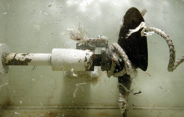
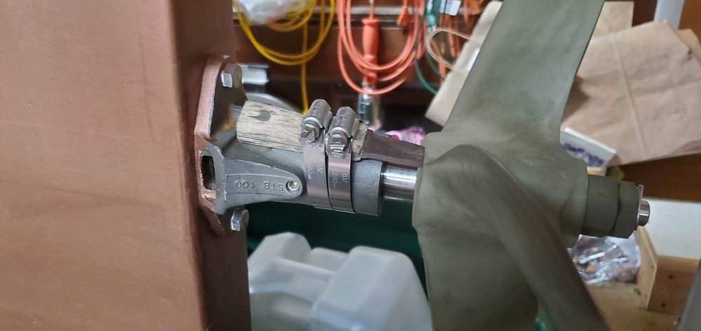
Thus the conclusion we would offer is that the backward sloping blades of the traditional propeller probably help in keeping the drive weed free but it is not guaranteed. There are other devices that could be employed as suggested in the Steamboating forum thread on Traditional Propellers. Shown is the shortened Steak Knife weed cutter installed by Kelly Anderson.
2. Building a simple version of a Traditional steam boat propeller
The traditional propeller that was fitted to SL Frances Ann was one of the Beckmann Boat shop 18” X 28” narrow blade range. Conversation with another SBA member who was interested in the technology of propellers and their relative dimensions led to a tracing being taken on A4 metric graph paper which captured the basic shape and also the area of the blade. Having not seen the Member since it was sent to him, there is no evidence that he found it useful. However, in a recent conversation with John Emmett it was learned that he was planning to build a different propeller for SL Snipe probably based on the traditional shape. John was pleased to receive a copy of the tracing and set about putting it to use.
The guide to making one’s own propeller in Steam Boats and Modern Steam Launches written by Weston Farmer (September-October 1962 p. 18) provides a graphical solution to getting the ‘twist’ of the blade correct. Thus for Frances Ann’s 18” X 24” propeller the following would seem to apply:
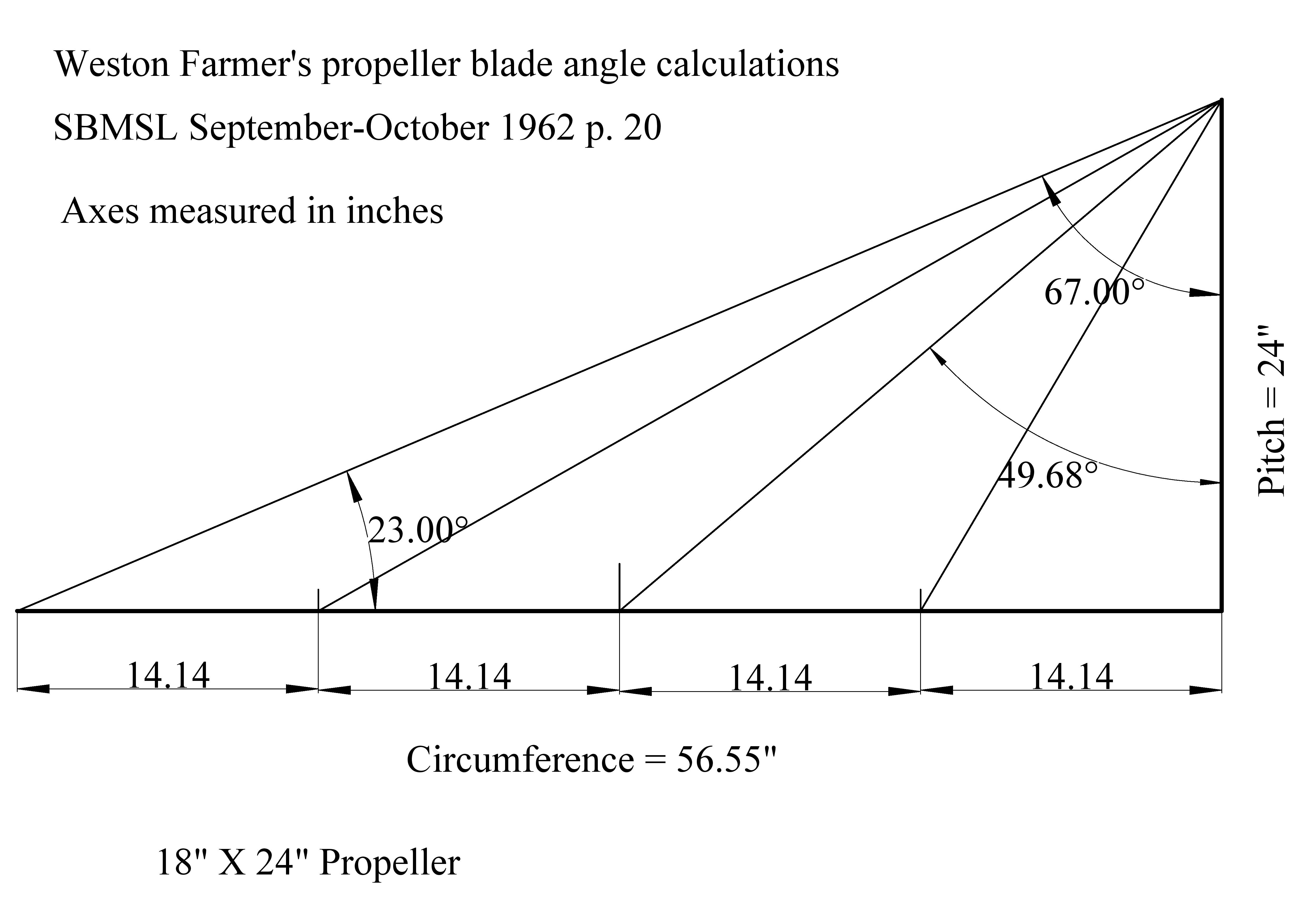
The diagram shows that the angle at the tip of the propeller should be 23 degrees from the plane of the propeller, that is, at right angles to the propeller shaft. Perhaps easier to understand is that the angle is 67 degrees from the line of the prop shaft. (Top right corner) The figure was checked in 3D CAD by drawing an 18” X 24” helix with a single spiral which maps the theoretical movement of the propeller tip through the water. This is shown below:
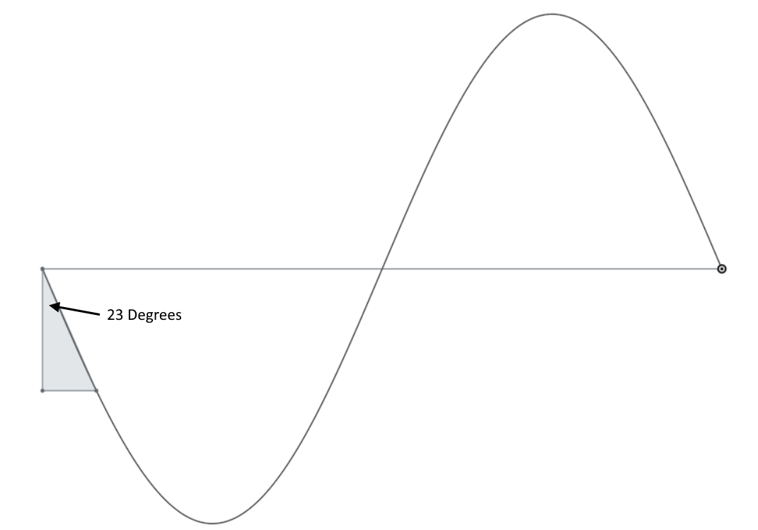 Thus the Weston Farmer diagram is a very useful and simple to create tool for getting the correct ‘twist’ at the end of the propeller blade. It should be noted that Mr Farmer’s four diagonals are arbitrary in that he was balancing ease of construction with obtaining a suitable profile for making a wooden mould for a cast propeller. The angles of the four lines show the angles of the blade of the propeller at quarter diameters from the centre of the shaft. Where a cast blade is planned then the rest of Farmer’s guide must necessarily be followed to get the shape of the mould right. However, assuming that the DIY propeller is made of sheet metal and the twist is done by fixing the base in a vice and using a suitable clamp at the tip and then twisting, possibly fewer diagonals could be used as is shown below.
For those reading this who are young enough to remember going to school and studying Geometry, the faint echo of Sine, Cosine and Tangent might be heard from looking at Farmer’s diagram. With a touch of revision of such terms it becomes easy to develop a spreadsheet that will provide the tip angle for any entered diameter and proposed pitch.
Such a tool can then answer the next question which is what happens if one scales the design down to the sizes that are suitable for small boats and canoes. While the ratio of the diameter to the pitch is held at 3:4 then the angle at the tip remains the same. However, seeking a different pitch will lead to a different angle. For clarity Weston Farmer’s diagrams are used for a 12” X 12” and a 10” X 14” propeller and are shown below:
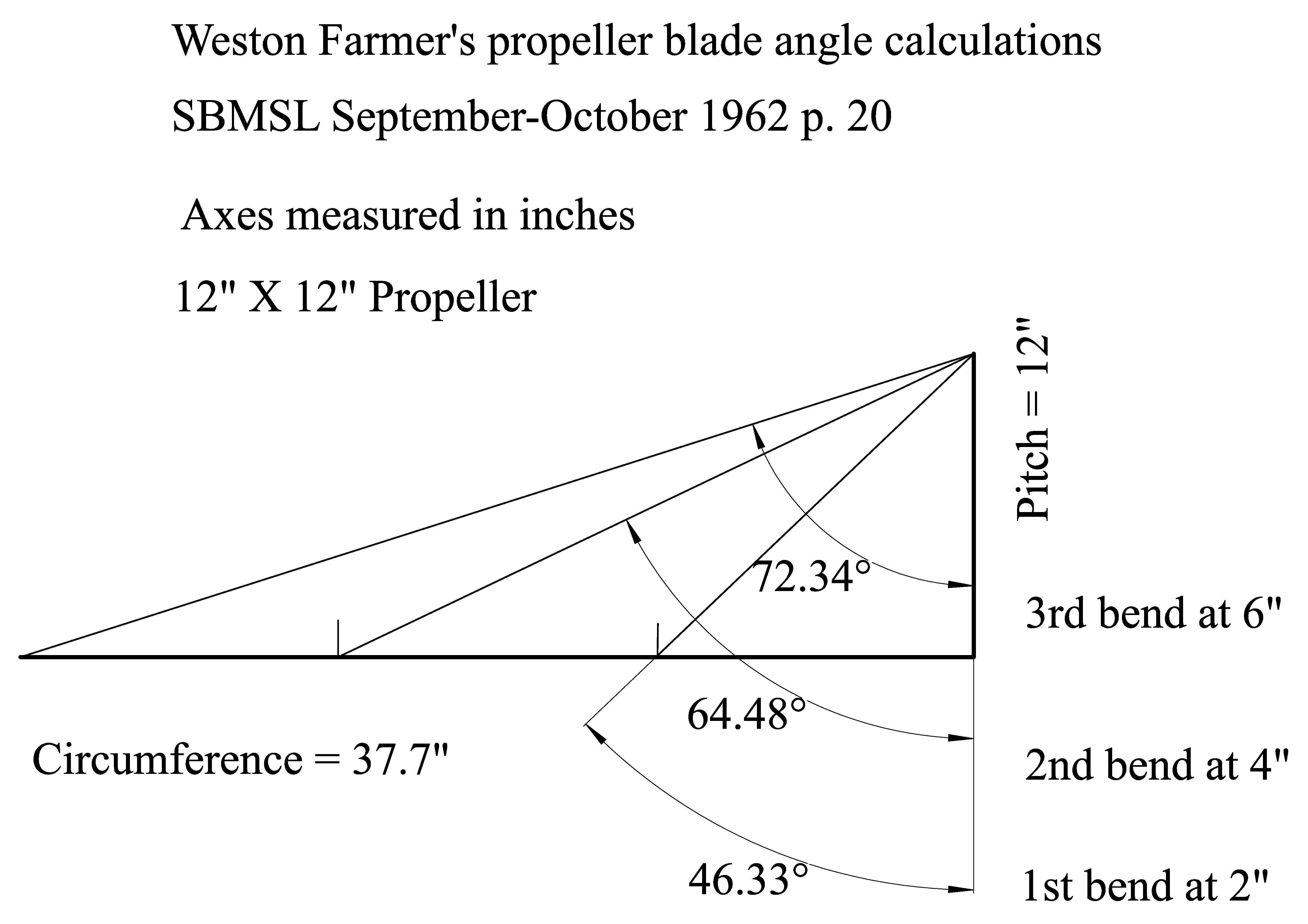
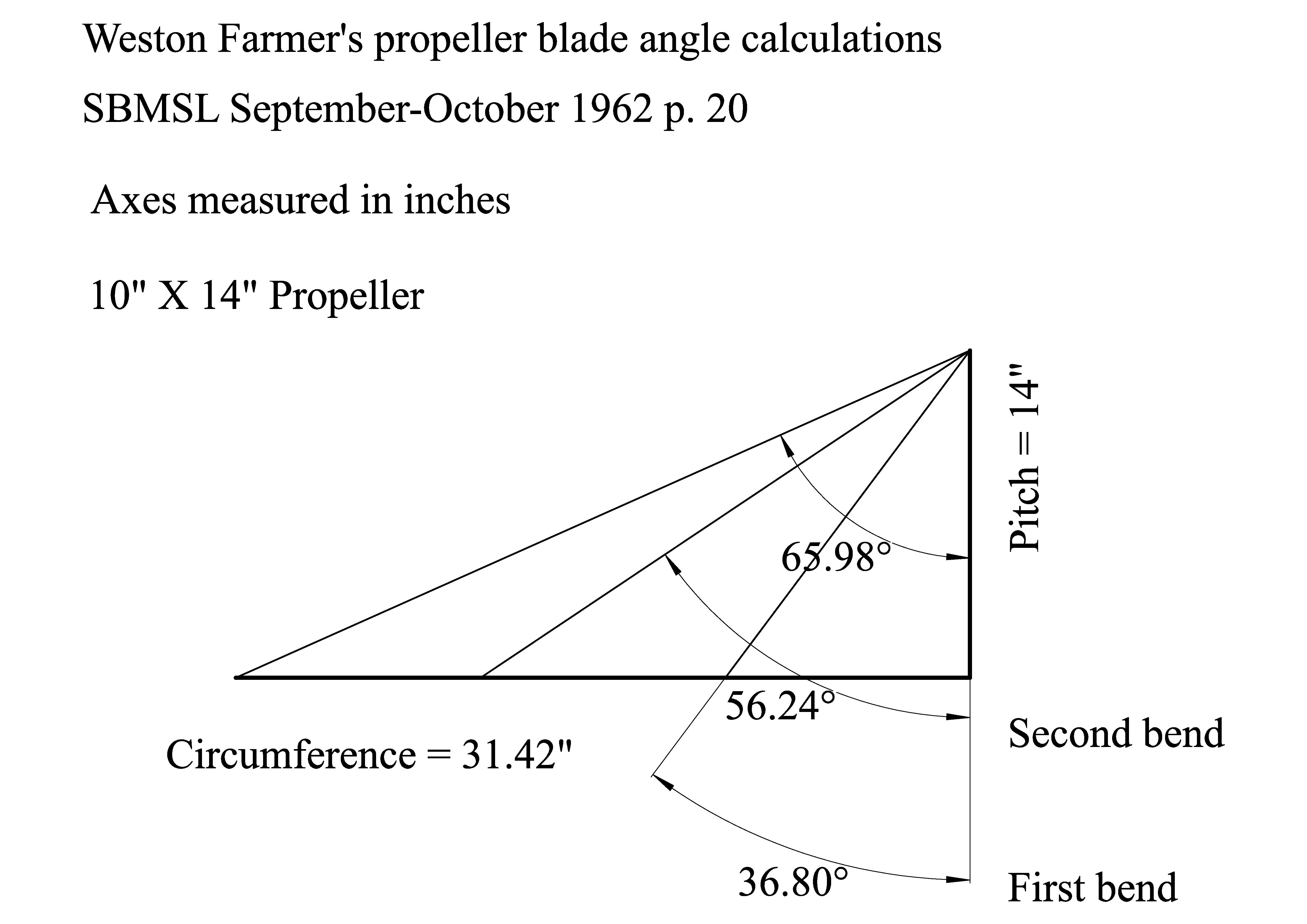
In both cases it has been assumed that only three bend checking points are required.
For the construction of the DIY replica John Emmett took the Frances Ann blade tracing and adjusted it to fit the proposed diameter of the replica propeller which in this case was 12” X 12”. The original propeller was nominally 18” in diameter with a hub that was 2” in diameter thus the single blade should be 8” in length (See below left). Seen out of context the profile looks somewhat confusing, but if the straight hub connection is lined up horizontally the dimensions become clear.
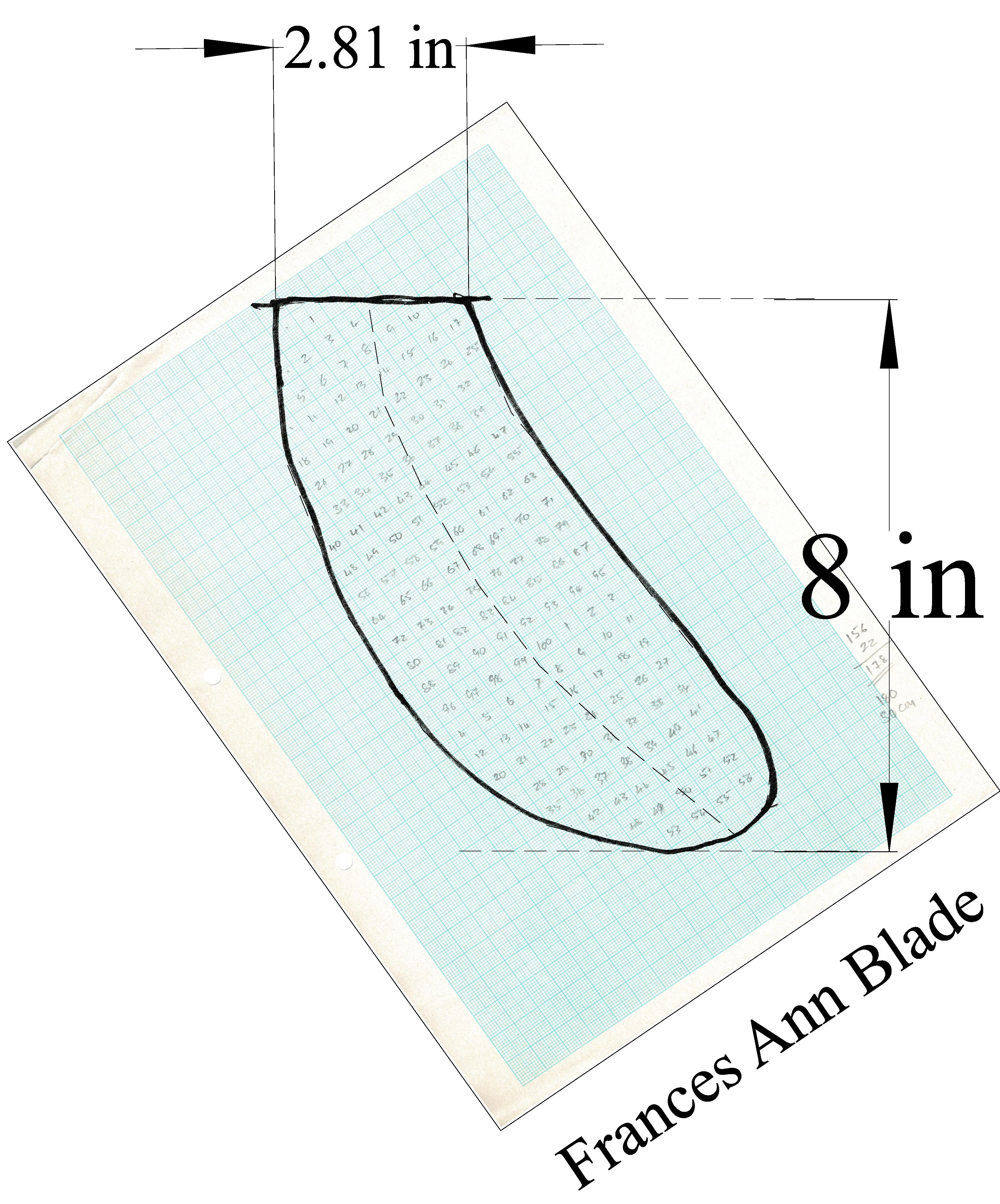
The next issue was to decide upon the dimension of the hub. For a proportionate reduction of the diameter from 18” to 12” the hub would need to reduce to 1.3”. However, that raises the question of whether such a thin hub would be strong enough for supporting the blade and to allow the connection of the drive shaft.
John sidestepped the issue by taking a different approach. He chose to use a triangular section hub milled down from round brass bar. This provided three flat faces onto which the base of the blades could be screwed and ultimately silver soldered. This approach meant that the blades could be set up as 6” blades, plus a little for fixing. This dimension being from the notional centre line of the propeller shaft to the blade tip. Note that the screw holes were offset up and down slightly to give access to the thicker metal away from the drive shaft line.
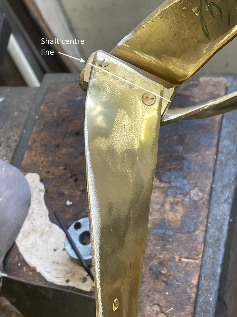 To achieve the appropriate blade profile the Frances Ann profile was ‘shrunk’ to 0.75 of the original size. This is a simple task for those with access to CAD but rather more like hard work when done manually.
Once the revised blade size was made it was then drawn onto ¼” brass sheet and three copies were created. These were clamped and then fettled to ensure that they were identical. With that done the bottom straight edge was clamped in the vice and some serious heat was applied to the trio. Once hot it was then possible to clamp a couple of bars, (or a large adjustable spanner,) at the first bend point and apply the initial twist. A useful gauge to assist in this is a simple folded sheet of metal onto which the angles of the bends are marked. The start of the markings needs to be aligned with the centre line of the blade in the vice.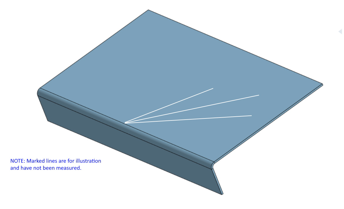
John reports that after the first bending which required the blades to be heated, the subsequent two bends could be performed without additional heat.
The three blades then needed to be cleaned up and the edges chamfered with a file or angle grinder. Depending upon the time an inclination available this task could include asymmetric chamfering to provide a small degree of aerodynamic profile. The next step is to mark up the propeller shaft centre line at the base of the blade and then mark and cut and countersink the two screw holes. With this completed for all three blades the holes for the screws need to be measured, marked up and drilled and tapped in the boss. With all that done the primary assembly is possible and some idea of whether the construction has been accurate enough to give a balanced propeller.
Assuming that a satisfactory balance exists and no blade needs extra material soldering back on, the final step is to silver solder the blades to the hub. After a further balance check the remaining task is to polish the propeller to show off the handiwork and metal.
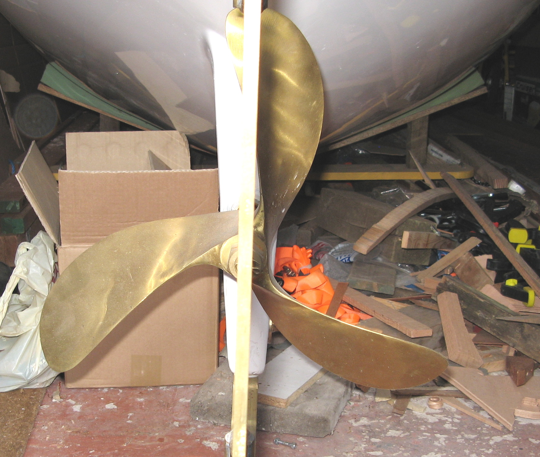
T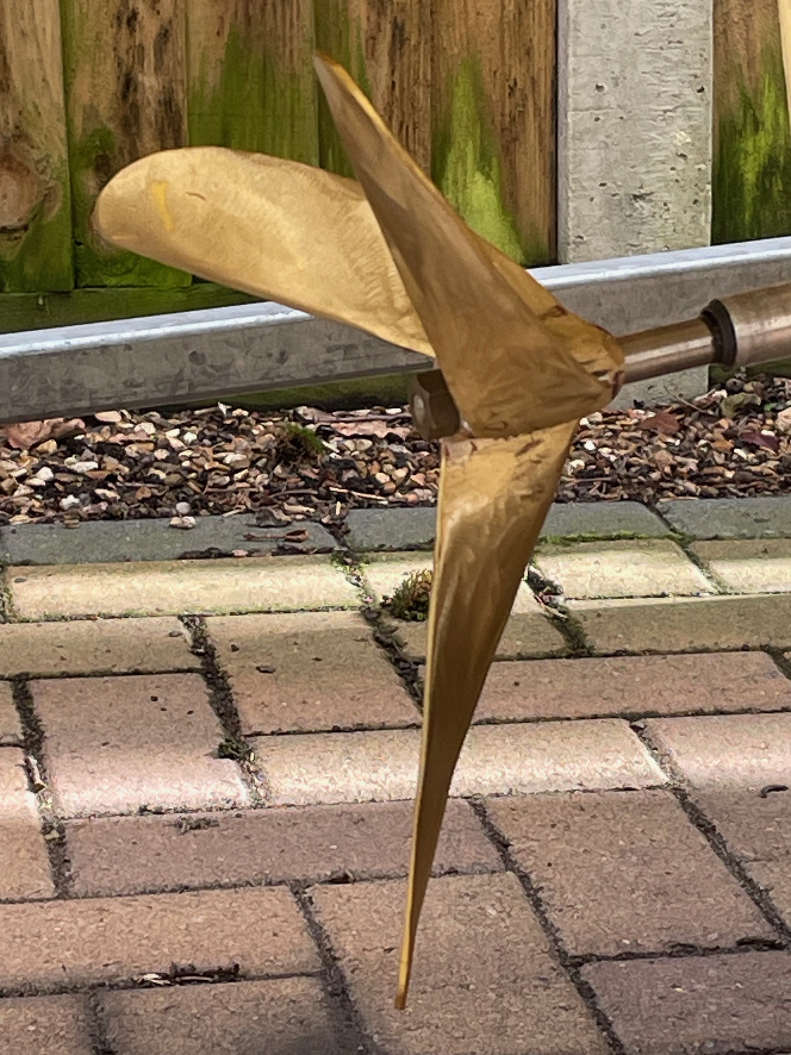 he final photo shows the finished blade fitted to SL Snipe.
© 2024 John Emmett & Pete Cuthbert
Previous: Propellers and Weed