Introduction
This section has two purposes. On the one hand it provides an eclectic group of comments about various pieces of equipment that might be useful for your mono-tube steam plant. The second purpose is to home in on one or two recent successful mono-tube plants and explain in copyable details how their control systems work and which electronic components were used. To go to the latter section, please click here, or to go to the other section please scroll down the page.
1. Pumps;
"Cordless" pressure washers have been advertised for a couple of years, and are often available without accessories on sites such as Alliexpress.com and eBay. The surprise to me is that the innards are usually different, rather than clones;
Here are three stripped and modified quick change versions;
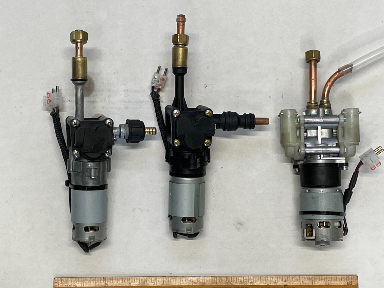
Supplier Example : https://www.aliexpress.com/ One needs to set up an account, log in and then search for Fandeii Shanglin Motor Store and look for Plunger Pump. This link may work: Plunger Pump These look like an updated version of the above pumps. Well made and inexpensive (IRO £15 GBP).
Suggested Search Criterion: Battery Water Gun Motor Car Washing Machine Pump
Whatever the voltage, these can all be driven safely by using a 12 volt nominal source and a Switched Mode regulator like this;
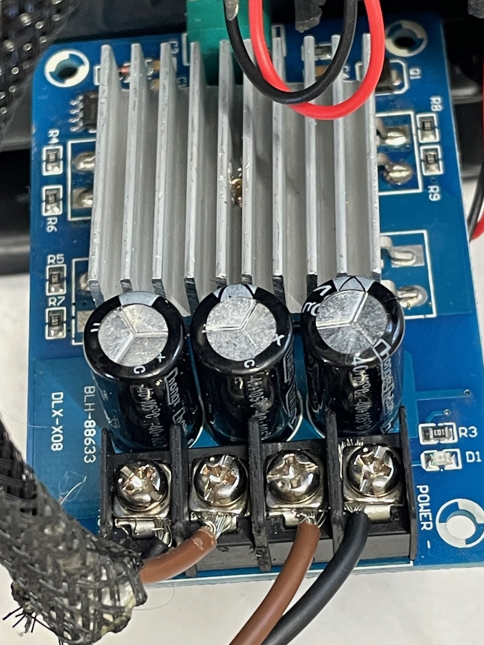
Supplier Example: 12V 24V 10A PWM DC Motor Speed Controller but these listings change quite rapidly. Similarly the design of the boards seems to change quite quickly so the design above is quite out of date (As at 5 June 2024)
Suggested search criterion: "12V 24V 10A PWM DC Motor Speed Controller Adjustable Regulator Dimmer Switch"
Typical output would be 10 - 80 litres per hour at up to 20 Bar, quite an improvement on plastic diaphragm pumps!
This article is stolen from Piping Engineer which is a very interesting site. Not sure how it is funded but it is very professional and chock full of information so well worth a look.
2. The Thermodynamic Steam Trap
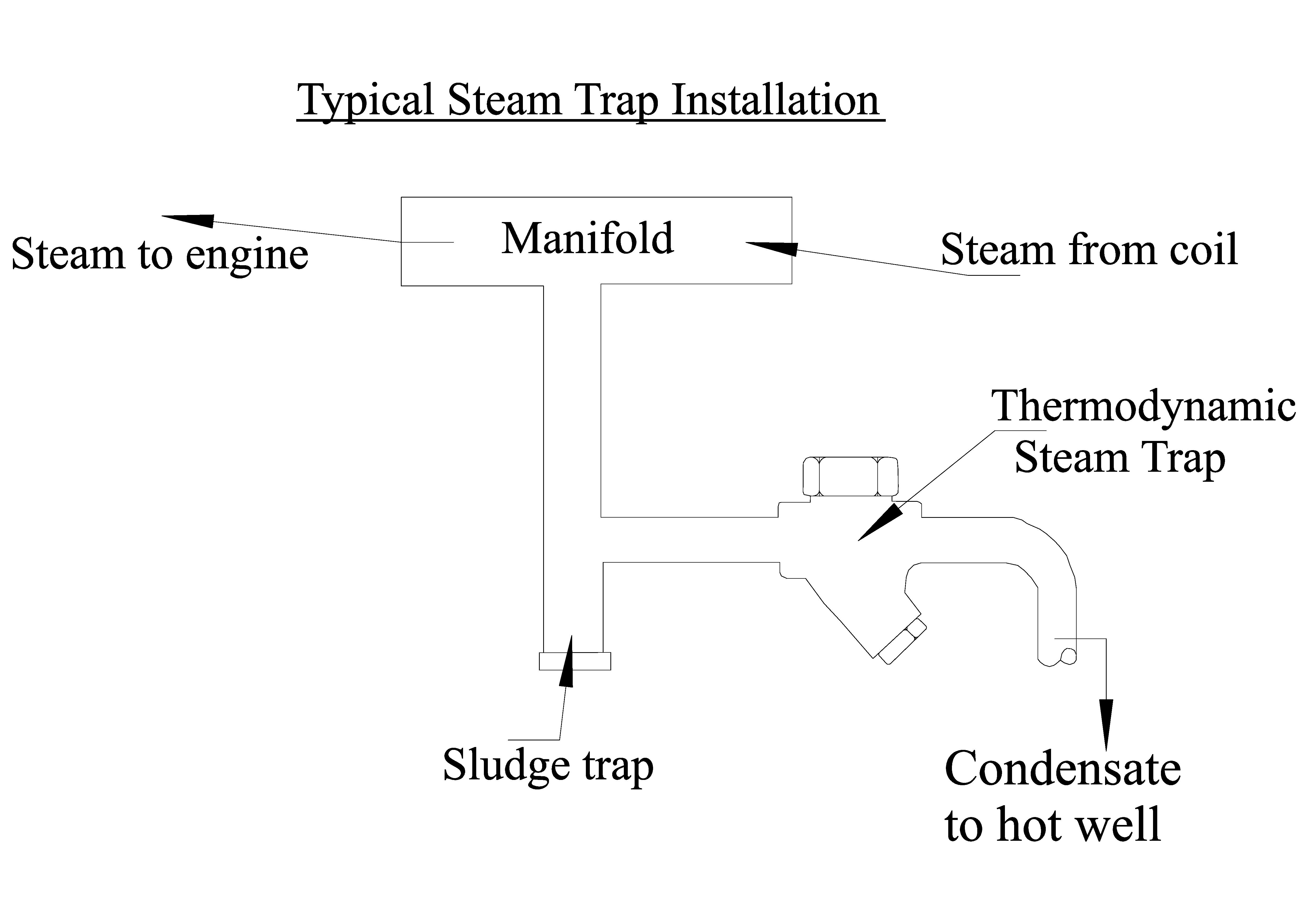
Thermodynamic steam trap is Kinetic Energy Operated Trap which requires no external power or other intervention to periodically drain condensate. It is thus idea for the mono-tube steam generator builder.
The thermodynamic trap is an extremely robust steam trap with a simple mode of operation. The trap operates by means of the dynamic effect of flash steam as it passes through the trap. The only moving part is the disc above the flat face inside the control chamber or cap.
On start-up, incoming pressure raises the disc, and cool condensate plus air is immediately discharged from the inner ring, under the disc, and out through three peripheral outlets.
Thermodynamic Steam Trap Operation Step 1
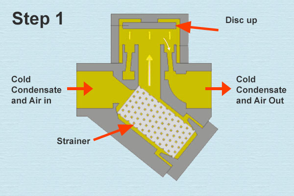
Hot condensate flowing through the inlet passage into the chamber under the disc drops in pressure and releases flash steam moving at high velocity. This high velocity creates a low pressure area under the disc, drawing it towards its seat.
Thermodynamic Steam Trap Step 2
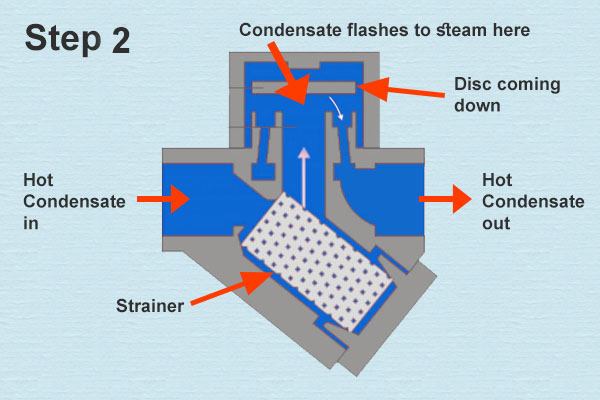
At the same time, the flash steam pressure builds up inside the chamber above the disc, forcing it down against the incoming condensate until it seats on the inner and outer rings. At this point, the flash steam is trapped in the upper chamber, and the pressure above the disc equals the pressure being applied to the underside of the disc from the inner ring. However, the top of the disc is subject to a greater force than the underside, as it has a greater surface area.
Thermodynamic Steam Trap Step 3
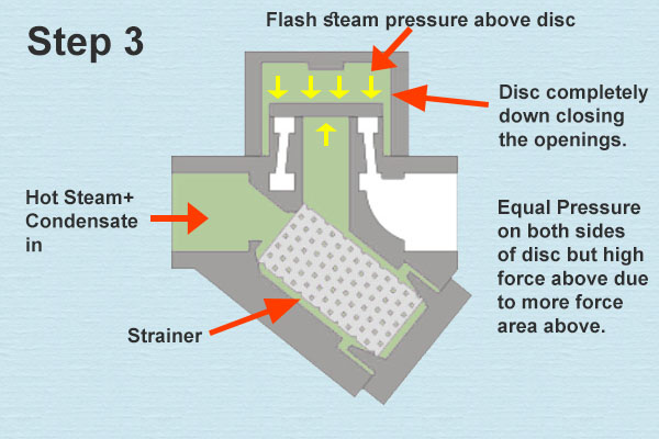
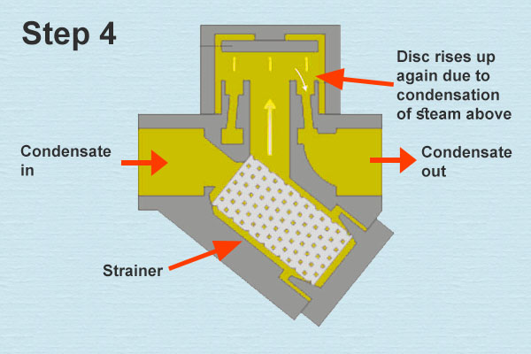
Eventually the trapped pressure in the upper chamber falls as the flash steam condenses. The disc is raised by the now higher condensate pressure and the cycle repeats.
Thermodynamic Steam Trap Operation Step 4
Some Pros and Cons
- As the disc is the only moving part, maintenance can easily be carried out without removing the trap from the line by just removing the top cap, which is bolted or threaded.
- Thermodynamic steam traps makes an audible ‘click’ which occurs during tap opening and closing. This makes trap testing very easy and straightforward.
- To close the disc inside thermodynamic steam trap, low pressure is required below the disc which is possible only if velocity of flow below the disc is high. Higher velocity requires higher pressure differential. So thermodynamic steam traps will not work properly on very low differential pressures. They require a minimum inlet pressure of typically 0.25 bar g (3.63 psi). They can withstand a maximum back pressure of 80% of the inlet pressure.
- The discharge of the trap can be noisy and this factor may prohibit the use of a thermodynamic trap in some locations, e.g. outside a hospital ward or operating theatre. If this is a problem, it can easily be fitted with a diffuser which considerably reduces the discharge noise.
- Oversize thermodynamic steam traps can increase cycle time and cause increased wear of trap.
Given all the above it really looks as if the Thermodynamic Steam Trap is a MUST HAVE for those mono-tube users who operate over feed systems and use a steam separator to get decent steam for the engine. The only downside would appear to be the price. As of today there were a couple on eBay for £50 GBP and £70 GBP respectively. Purchased new the price is in the region of £250-300 GBP. They are also available from China and India and a request to the Made in China website has yet to turn up a cost for a small capacity unit shipped to the UK.
PC 7th January 2024
3 Safety Valve - Seeking a Safety Valve
The safety valve is probably one of the most important pieces of equipment that will be connected to the mono-tube. Its purpose is to ensure that the mono-tube does not build up a pressure that could lead to the catastophic failure of components such as manifolds, steam separators, etc. For most mono-tubes it is unlikely that the coils would fracture but the joints are potential areas of weakness. The safety valve is also the tool that can maintain the system at a steady pressure by venting excess steam until normal operating pressure returns. Such a practice is reasonably unlikey in a well managed system where the heat input and water input are set to provide steady state operation. However, it is always possible that such an equilibrium might be disturbed by unexpected external events and the safety valve could become very useful. A further important factor is that insurance companies, boat clubs, etc. require a certified functioning safety valve for all steam plant.
The Basic Technology
 The diagram shown has been stolen from Piping Engineer, a very interesting information site for those interested in steam. It is not clear who operates or funds the site but it is a great educational resource.
The connection to the pressurized area is at the bottom (shown in red) and while the pressure remains below the set level the 'seat disc' keeps the valve closed. That is achieved by the pressure from the spring pushing the disc downwards. The spring pressure and hence the pressure at which the valve opens is set with the adjuster screw at the top. Most boat safety valves will have a wire and lead seal to prevent unauthorised users from adjusting the valve.
When excess pressure occurs the disc is pushed off its seat and the steam escapes out of the vent shown at the right. For most designs steam cannot enter the bonnet area where the spring is sited which avoids the problem of springs rusting.
In most steam boat settings the outlet pipe is usually arranged to run up the rear of the funnel keeping the excess steam away from the passengers and crew. There will also be a small hole in the elbow where the pipe goes from horizontal to vertical to allow condensate to escape rather than running back to the safety valve.
Inveno Engineering Inc. in their best practice guide for safety valves stress that the outlet pipe must be securely mounted so that its fixings can support the weight of the outlet pipe run without placing any load on the safety valve. They argue that placing a load on the safety valve could over time compromise the security of attachment of the safety valve.
As has been reported elsewhere, much work has gone into the building of the Fairlight 406 mono-tube boiler casing and coils. The next stage is the manifold which has been designed and is under construction (June 2024). However, it is necessary to have all the components to hand when they are needed
Getting a valve to suit the mono-tube boiler was not something that was expected to be a problem as other folk with small mono-tubes had them. However, two mono-tube builders who were consulted about possible sources reported that they made their own safety valves. This came as a surprise but having neither the skill nor the time to go down that route a ready made valve was required. A rough list of ‘appropriate’ safety valve characteristics was made up including UK or European made, bronze body, lift lever, pressure settable to 90psi (6.2 Bar), approved for steam, small in size and ‘looks the part’. Then the Internet was used as the tool in the search for some potential suppliers.
As might be expected this search yielded Johnson Valves, Leengate Valves, Safety Valves online, Valvesonline, Albion Valves and many others. What quickly emerged was that many of the sites are simply dealers while the actual manufacturers are few.
 |
| Figure 1 – Gresswell valves – G90 and G100 |
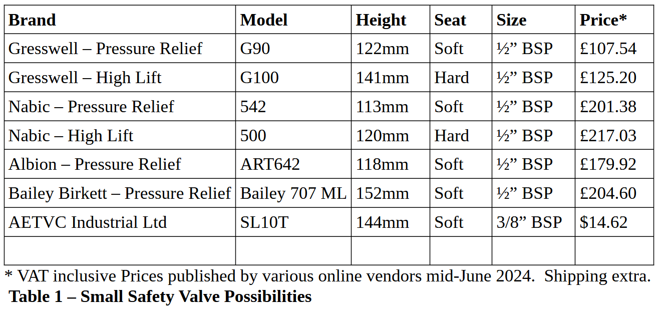
Gresswell is a UK manufacturer based in Telford and have two valves that looked appropriate. The first was the G90 which is a ‘soft seat’ proportional lift safety relief valve designed to allow small flows of over-pressure gas. The second was the G100 which is a ‘hard seat’ high lift valve that will dump a lot of pressure quickly. In terms of price these were offered by Valves online for £107.54 and £125.20.
|
|
| Figure 2 - Nabic 500 and 54 |
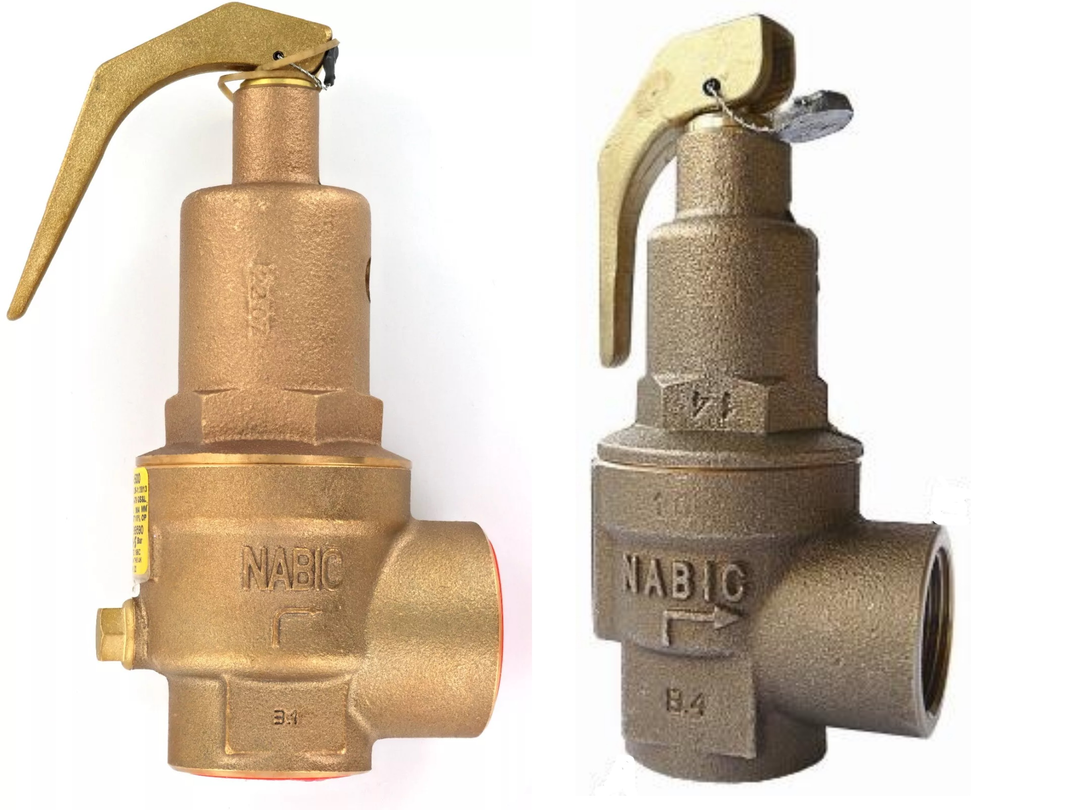
Another UK manufacturer is Nabic, a company with a long history of involvement with pressure vessel safety. The Nabic 542 is a safety relief valve priced at £201.38. The Nabic 500 is a high lift safety valve priced at £217.03
Albion (UK) Ltd was a company I had not seen before but its website seemed to imply that its safety valves are UK produced but does not actually state where they are made. They have one product that seemed to mostly ‘fit the bill’, the ART 642 which seems to retail at £179.92
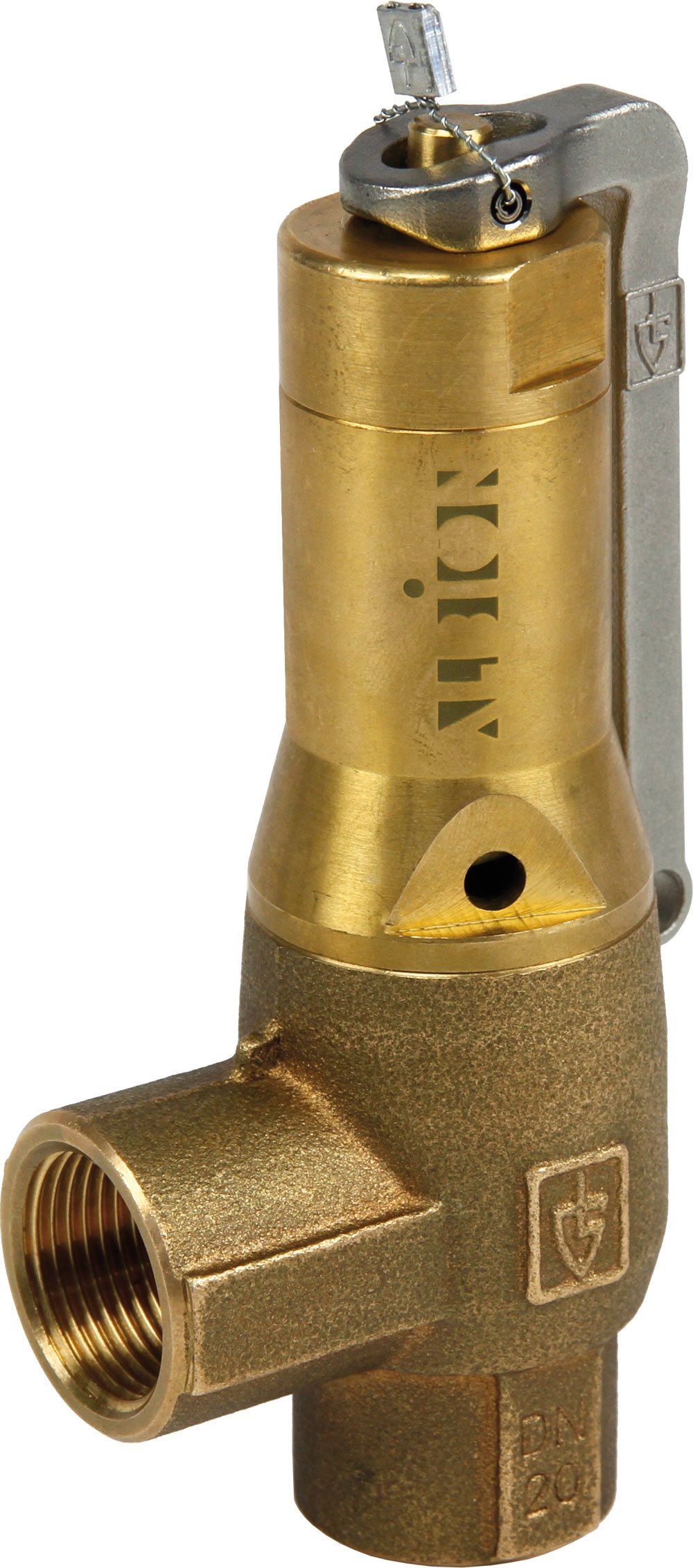 |
| Figure 3 - Albion ART 642 |
A brand well used by the SBA fraternity is Bailey Birkett. This is a business with its origins in 19th Century Manchester but with a tremendous list of takeovers and name changes since. They appear to have one valve that could be suitable, the Bailey 707 ML, priced £204.60. At 152 mm the 707 is probably the biggest of the valves examined.
 |
| Figure 4 - Bailey 707ML |
In this research process I discovered that there are two basic types of safety valve for SBA type use. The first is the high lift pressure relief valve whose design purpose is to reduce pressure as quickly as possible. They are also listed as ‘hard seat’ valves as the spring loaded closure disc closes on a well ground metal seat. Ensuring pressure tightness requires extra precision and thus these valves tend to be somewhat more expensive.
The other type, the pressure relief type safety valve is more concerned at keeping the system stable and close to the required pressure without leading to a depressurization event. These are often labelled ‘soft seat’ safety valves as the sealing disc closes on a PTFE or similar ‘washer’. These are easier to make and are thus somewhat cheaper.
In practice they are probably better for steamboaters as they will pop open and then close again when pressure is close to the limit. High lift safety valves can get over enthusiastic and dump too much steam quickly emptying the boiler of water which I had discovered with the one on Frances Ann.
With that better understanding it was clear that my list should be reduced to the soft seat valves only. The other issue that was nagging me was that all the vales seemed to start at ½” BSP and none were smaller.
However, while this was going on I had enquired of Made-in-China whether there were any businesses selling safety valves. I was surprised that they were willing to allow me to register as they are actually a Business To Business organisation not focused on the retail customer. They sent me lists of valve making firms all of which had long lists of products. Eventually, I stumbled across a safety valve all in stainless steel that looked roughly what I was seeking. I chased them for full details and then tried to twist the arms of a few technical SBA Members with whom I am in a correspondence relationship to give me their views on suitability. The comments were few and that route rather died the death.
Given that plenty of other things were going on in my life the only other decision I made was to see if any of the UK suppliers could do their products in 3/8” since they almost all specified in their advertising that 1/2”BSP was their smallest. The reason for the request was that the mono-tube boiler has a ¼” OD outlet pipe from the coils and a ½” safety valve orifice is way too large. The response to my queries was underwhelming. Nobody bothered to reply.
However, Made in China are a pushy organisation and continued to bombard me with emails. One afternoon I idly followed up one of their recommendations and was surprised to find bronze bodied safety valves looking just like the European ones. Homing in on a soft seat product I was amazed to find that the size listing went down to 3/8” BSP. The site stated that the firm was Shenzhen AETVC Valve Company Ltd and the sales person was Miss Sally Zhu. Using their online form I asked whether they would sell a single unit and ship it to the UK. Also if that was the case what would it cost. The answer came back very quickly, in good English, that the cost was $14.62USD and shipping would be $36USD. Payment would need to be by bank transfer or PayPal. I think I should point out that Sally was very patient and helpful given that this was essentially a trivial one off sale possibility.
It was at this point that the great British Banking Rip Off stepped in to make life difficult. Not having a PayPal account, but having an HSBC branch in the town, which is the same bank that the Chinese company use, I decided to make a visit taking the Pro-forma invoice with me. No was the answer, we will not take money from you and pay it to one of our Chinese branches. You are not a customer! Fortunately, three doors down was the bank with whom we have an account; Santander – the Bank That Likes to Say No. Wielding the proforma invoice I popped in to see the nice ladies who staff the desk. Oh, yes. We can do that for you. There is however a fee of £20. Could I do it as an online bank transfer from my computer? No, Security would prevent it. You could do it by phone using the International Transactions Department, but of course they would charge you £20 too.
Thus I had to squash my doubts and sign up to PayPal. That was not a pleasant experience and not something I would recommend. However, it eventually worked and I placed some money in my ‘wallet’. The final step of paying Sally’s company was very easy and the total charges were zero. On arriving in the UK the parcel caught Customs Duty of £9.61 but by the time it arrived on our doorstep the total outlay was £51.18.
The final product is a really nice looking object that is clearly well made. The advertising material shows that the technology differs little from the UK made safety valves and thus I am hopeful that it will perform satisfactorily. At the time of writing (mid June 2024) the mono-tube boiler is nearly complete but currently needs the manifold building and installing before the valve can be tested.
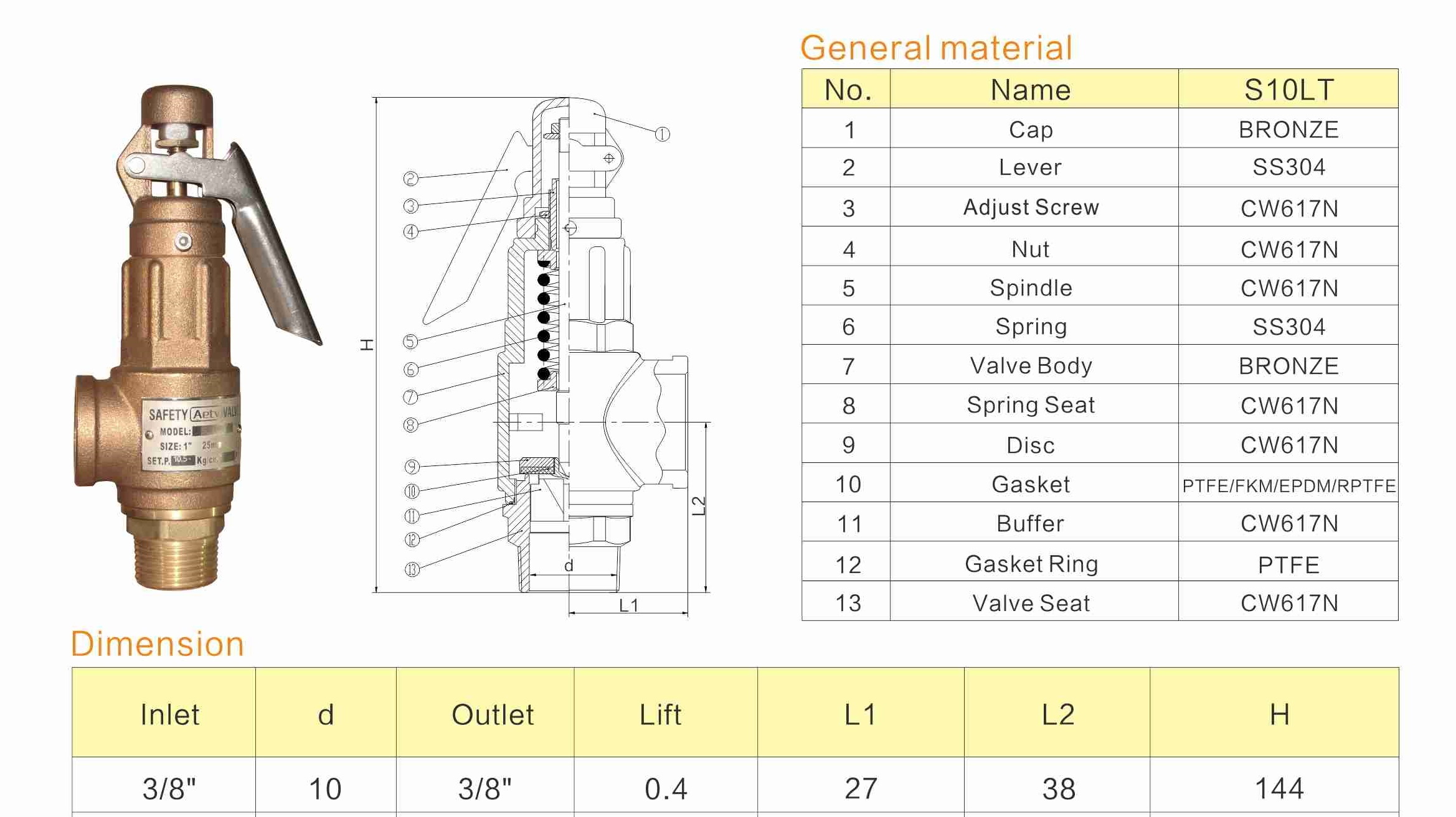
Figure 5 Shenzhen AETVC Valve Company SL10
References
Mike Robinson (2008) “The Steam Canoe Taniwha”, Funnel - Issue 138 Autumn.
John Emmett (2023) “Developing the Boiler for Snipe”, Mono-tube.org.uk
NOTE: All graphics are taken from manufacturers’ advertising materials and are thus their copyright.
Next: Hulls
Previous: Fires
4 . Whistles and Whistle Making
This is an area that might grow as people offer their views and suggestion so we have set up a separate page which is to be found here.
5. Making low cost hand pumps
As a minority of readers may know, a small mono-tube boiler has been taking shape in the garage here for a very long time. Surprisingly, especially to the constructor, completion is possibly in sight. That, of course, means that one has to think about what comes next. High on the list is the hydro test and then there is the issue of the other components besides the engine that will be required to turn this heap of metal into a working steam plant.
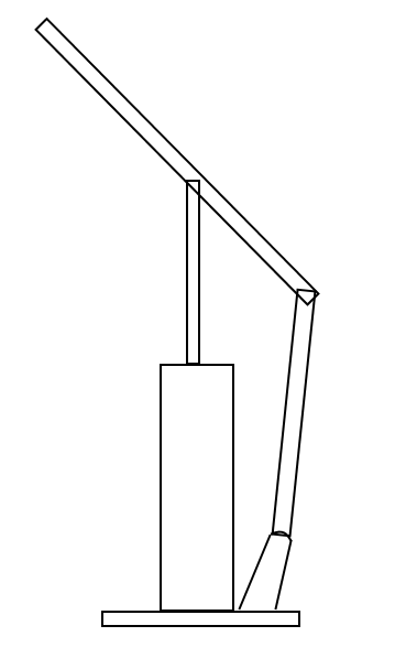
The hand feed pump rose to the top of the list and some scouring of the various online and offline sources was begun to find a design. Unfortunately, the wonderfully ‘over top’ hand pump bought from Beckmann Boatshop in the USA for Frances Ann appears to be no longer available. Typically, the extensive photos of that launch failed to include a good photo of the pump. However, there were a number where the pump is partially visible and so a ‘back of fag packet’ sketch could be assembled: (Fig 1)
 |
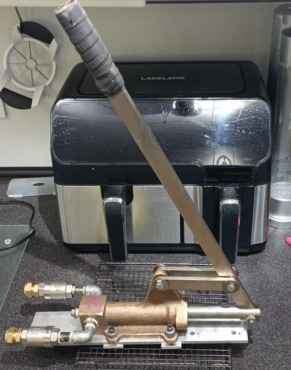
Various other sources including the SBA website, the Steamboating Forum and the SBAS pages were examined. The requests yielded nothing useful initially, but SBAS provided a price for their casting which was many times more than it seemed sensible to spend on a down market project like this. Their pump, when machined up, is magnificent as is shown below: (Fig 2)
 |
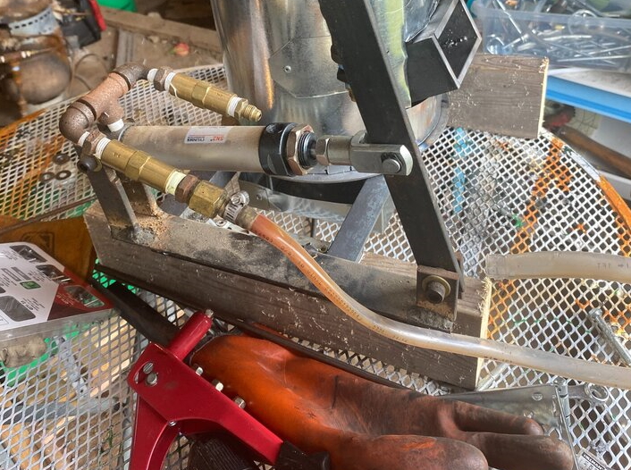
Next a newcomer to the Steamboating Forum, Rolph, saw my request and pointed out that one could build an inexpensive hand feed pump from pneumatic cylinder parts. His photo (Fig 3) suggested that a horizontal pump would be quite simple to construct. Following his advice, eBay and AliExpress were searched and a multitude of cylinders were found to be available. The prices were astonishingly low and so a decision was made to buy one.
Given the huge range of sizes available a key questions was which size would be sensible? A small one might mean a huge number of strokes to fill the mono-tube, whereas a big one might fill it in a single stroke since its capacity, excluding the feed water heater, is only 0.138 litres (if the calculations have been done the correctly!). The solution seemed to be to build a spreadsheet with each of the available sizes and then see how many single acting strokes would fill the mono-tube. There was a degree of overlap in that short fat cylinders could pump as much as long thin cylinders. That made decision making somewhat arbitrary and so the preference for a longer rather than a shorter pump won the day, influenced by the original Frances Ann pump design.
 |
The decision on where to buy the cylinder was somewhat irrational too. The vendors on eBay seemed to have all the same cylinders as the vendors on Ali Express. However, the latter seemed to have a better algorithm for feeding ‘you might also want one of these’ items onto the screen. Thus the chosen pump size plus a knuckle to go on the end of the shaft, a couple of ‘horizontal’ mounting brackets and angled mounting brackets all ended up in the Basket. Dispatch and delivery were astonishingly quick and it is embarrassing to have to admit that high carbon footprint air freight must have been used.
 |
On arrival the package appeared to be rather larger than expected. When opened it was found that the contents included not one but two cylinders. A quick return to the Ali Express site of the vendor revealed that there was indeed a small (X2) in the description which had not been spotted earlier.
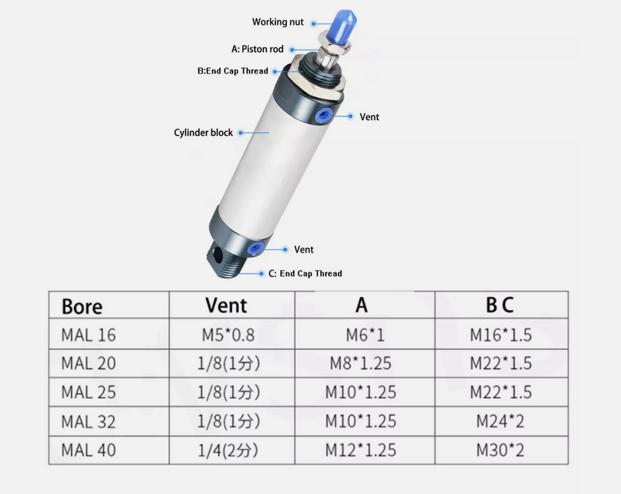
Examining the products it was clear that they are well made and fitted together nicely. The only issue was to find out what thread was used for the inlet/outlet ports. A message to the vendor led to a response that they are G 1/8” or 1/8” BSP. With that information to hand it seemed sensible to seek an adapter fitting to connect 1/8” to ¼” BSP as the latter is the standard used on this boiler. The adapter fitted nicely, but the hole through it was only 5.4mm. Consideration was given to boring this out to 6mm. Similarly the hole from the port into the cylinder is even smaller, about 3mm, and looked as if it would also benefit from drilling out to (say) 6mm.
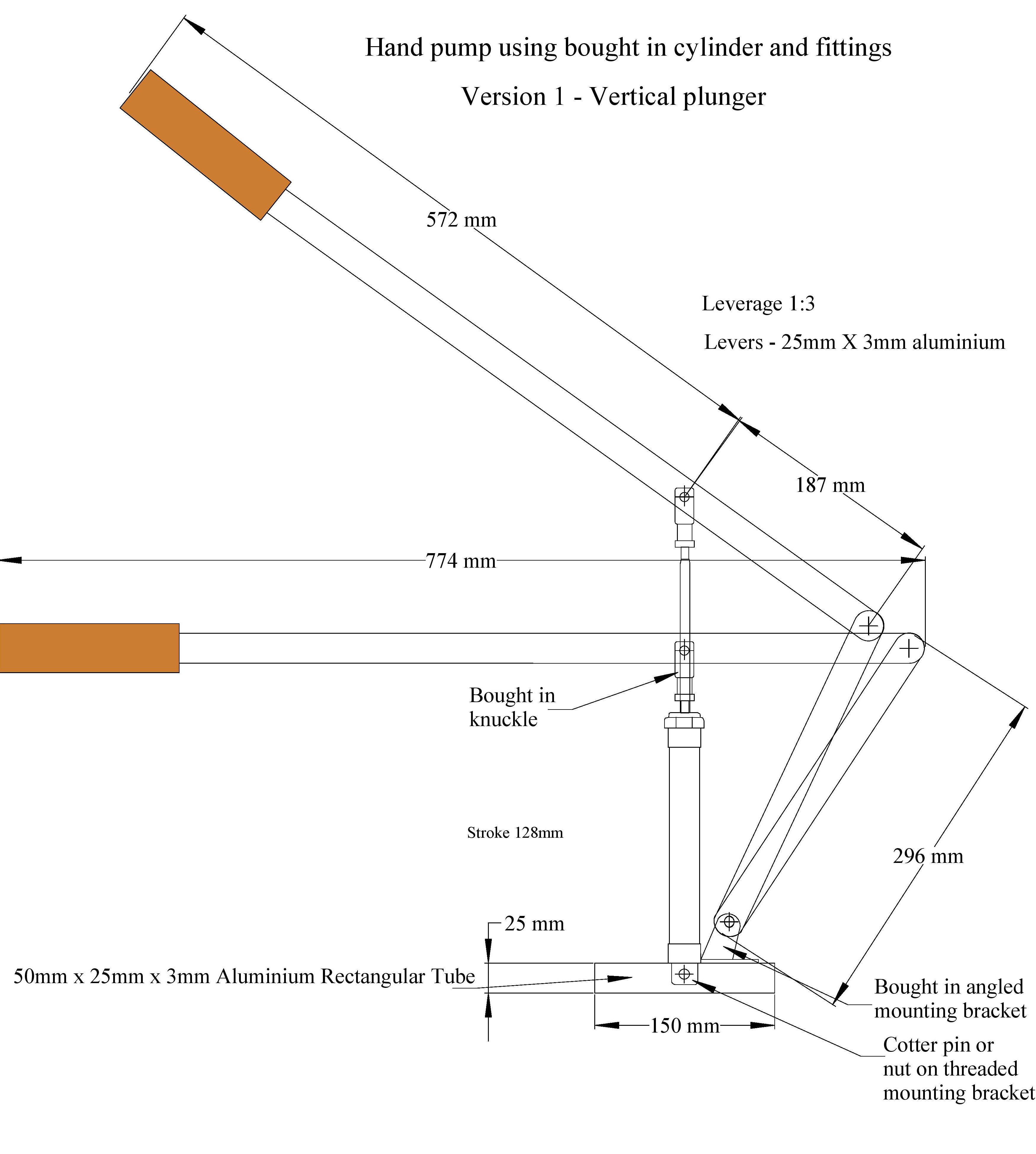
With the cylinders now sitting on the desk it seemed like time to get the fag packet drawing turned into a somewhat better 2D CAD drawing. There was some dithering over whether to jump straight to 3D CAD, but long use of 2D suggested that it was probably best for the first draft. The result is shown below in Figure 5.
 |
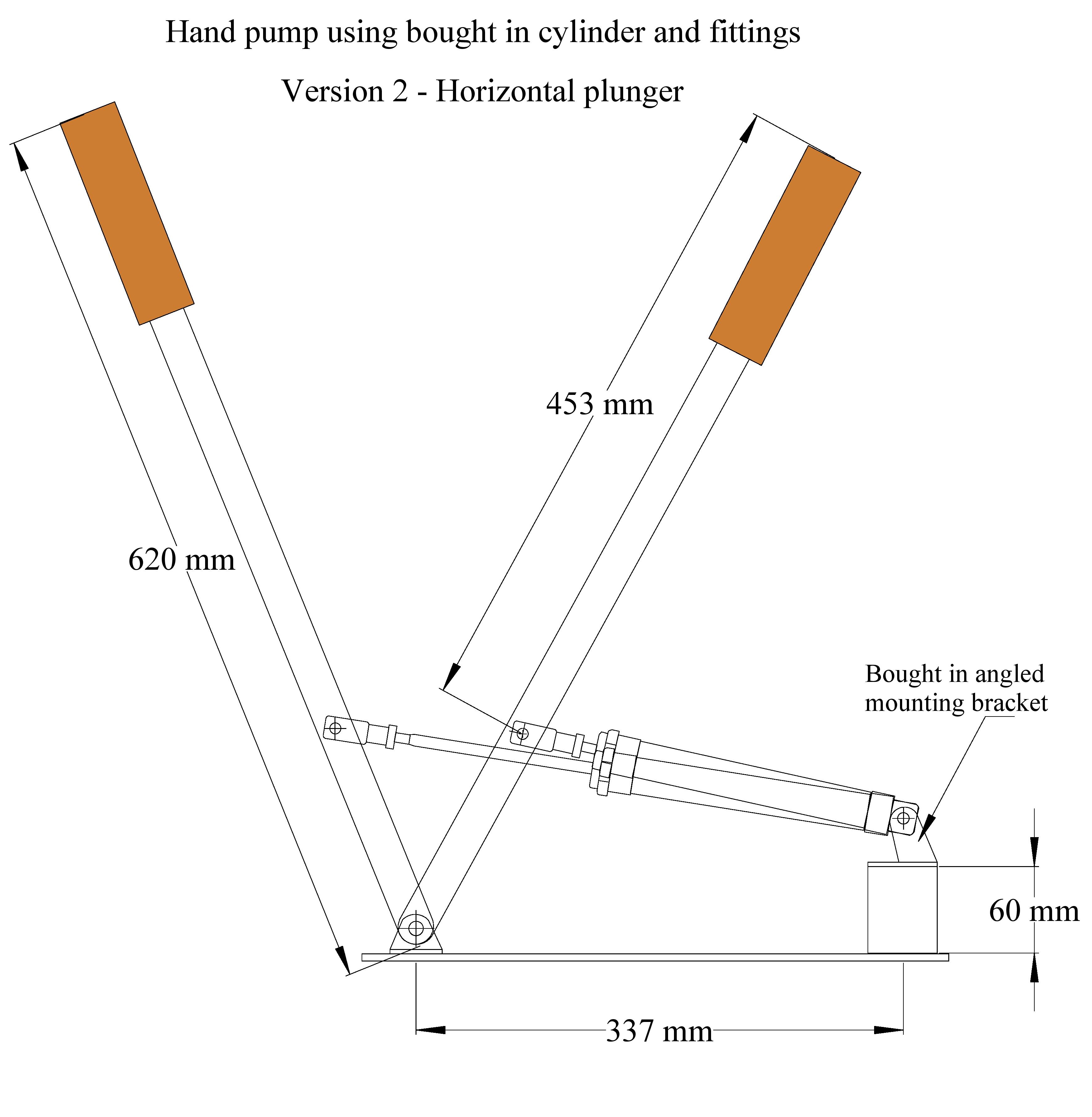
Having drawn the vertical version of the pump, enthusiasm for the cylinder led to the drawing of a horizontal version. Initially the concept was based upon the format used by Chris Doughty in “Made of Scrap” (Funnel Issue 198 - Page 59) and by the SBAS. However, glancing back to Rolph’s picture it seemed obvious that he had developed a much simpler horizontal design. Thus a ‘Rolph Pattern’ pump design was created as shown in Figure 6.
The approach to plumbing the pump used by Rolph also looked to be both simple and efficient and the parts to do the same were also ordered. Ali Express’s ‘you might also want one of these’ link furnished a pair of one-way valves in ¼” BSP as well as some more pump fittings. The latter were added as by now it had been decided to build both versions. After all, anybody thinking of following this example will need to know how the two designs perform.
It was decided that the handles should be aluminium rather than brass due to both cost and weight considerations. It was not too difficult to find 25 mm X 5 mm aluminium strip in sensible lengths, but often it was difficult to find what the vendor wanted for shipping. As a result a number of firms ended up with incomplete ‘orders’ where it was necessary to get as far as checkout before shipping costs were revealed.
 |
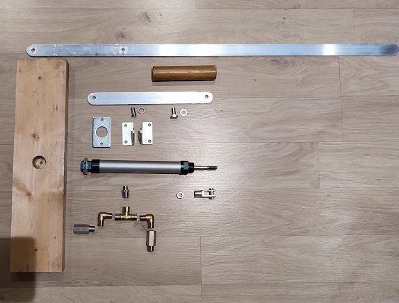
Once received, the aluminium bars were measured and cut to length and their ends rounded. The position of the pivot holes was marked and then centre drilled.
The bought in parts included bearing pins which were finished with spring clips in slots rather than Clevis pins. The one in the knuckle needed no attention, but the one for the angled bracket was way too long. Not having a tool narrow enough to replicate the slot for the spring clip the pin was drilled M2 assuming that a split pin or R pin would be used. It was then cut to a sensible length. The pins were nominally M8 and an extra one was required. Fortunately there is a large stock of left over M8 X 40 hex bolts and one of those was given a similar treatment.
For drilling the holes on the aluminium bars a search was made for an M8 drill, but that was not to be found. However, some old Imperial drills included both 7.8 mm and 7.9 mm. These were used and it was found that the slightly smaller holes meant that the pins were a nice tight fit which is ideal.
Once all the subsequent orders had been received it was possible to begin construction. The decision to bore out the 1/8-1/4 BSP adapter was taken and the bottom end of one of the cylinders was carefully unscrewed. It was good to see that the manufacturers had used some form of ‘Loctite’ on the thread for good sealing. The end casting stub was easy to hold in the vice and not too difficult to unscrew. With the outlet port adapter screwed into place it was possible to widen that and the port into the cylinder in a single pass. Care needed to be taken to stop the drill once it had reached the level of the inside of the cylinder. With that done the cylinder was reassembled minus any swarf.
 |
Not yet having a boat available it seemed sensible to mount the pump on a chunk of wood of which there is no shortage in the ‘may be useful later’ pile. That was cleaned up and then the centre of the piece was marked. First the 32mm hole cutter was used to make a hole to accommodate the nut holding the base plate into position. The depth was not critical but needed to slightly more than the thickness of the M22 nut. That was followed by the 25mm hole cutter going down to a depth equivalent to the stub on the bottom of the pump (22mm). The 25 mm cutter was used as the available collection does not include a 22mm cutter.
With that done the base plate was fitted to the pump and the first ‘issue’ spotted. With it fitted there was barely room for the port adapter fitting to be unscrewed. Clearly an M22 washer was needed between the pump and the base plate. Typically the vast collection of odds and ends did not yield the required part. In stead an M8 giant penny washer was bored out to M22. With that fitted there was just enough room for the adapter to turn.
The base plate was tightened up and then the unit was offered into the hole in the wooden base. The cylinder base plate could be installed at right angles or parallel to the wooden base. Parallel was considered to be the best so the centre line was marked and the screw holes punched. Two flange headed screws secured the assembly.
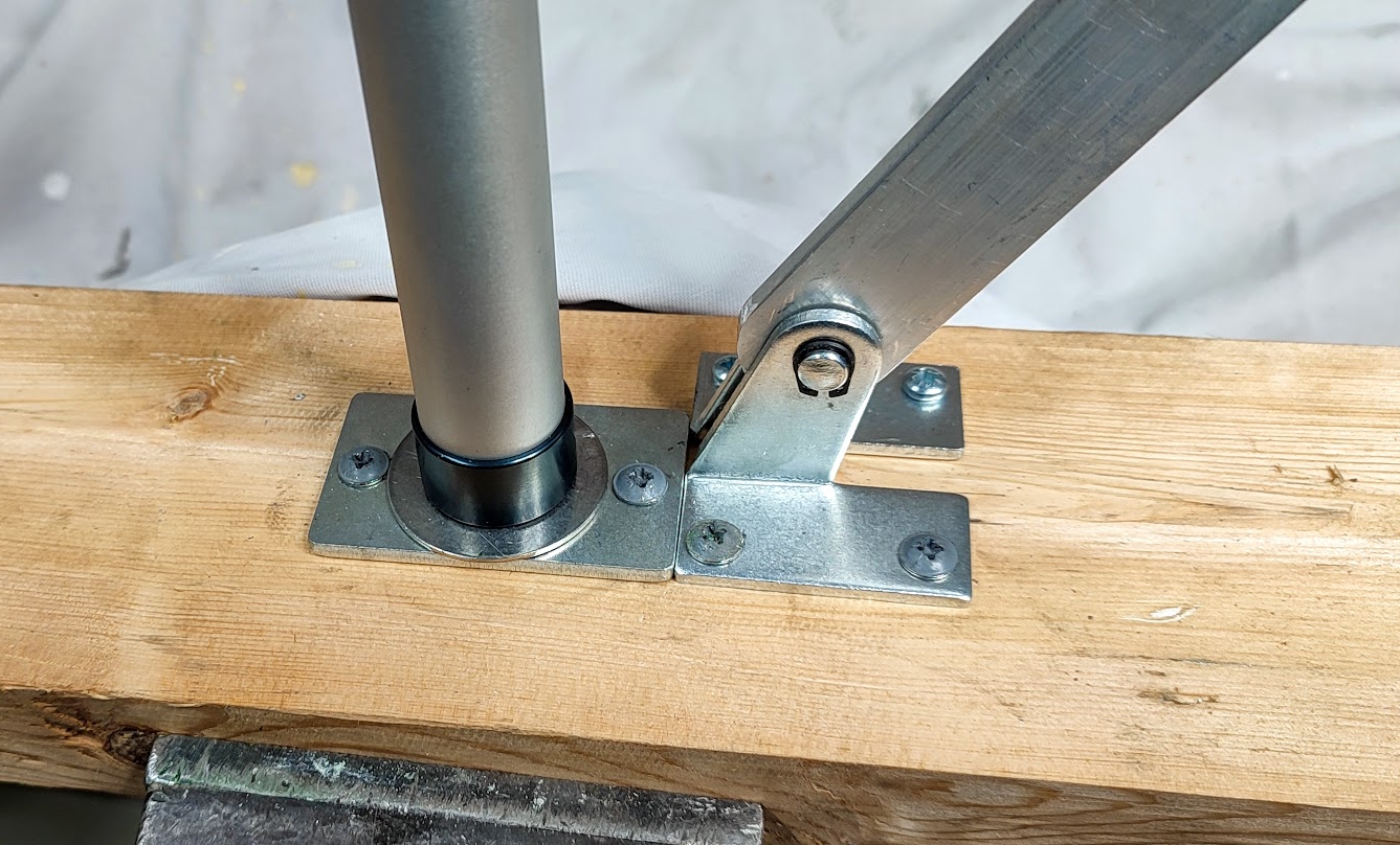 |
Next up was the pair of angled mounting brackets. The first impulse was to mount these along the centre line with a 5mm gap for the shorter lever. However, the main lever needs to be true to the centre line and the connection between that bar and the short lever is face to face. Thus the short bar needs to be off set by 5mm. This could have been avoided if a knuckle had been made for the end of the long lever, but that would have added to complexity.
The two brackets were positioned up against the cylinder with their slant away from the cylinder. Once again, the screw holes were piloted and then the brackets were secured with flange head screws. Next the short lever was installed with the Clevis pin secured by a bit of wire since the stock of split pins did not include M2. The knuckle was screwed up and locked on the pump shaft and the long lever attached with the other clevis pin and another piece of wire. Finally, the two aluminium levers were connected with the home made Clevis pin and the main elements of the pump were finished. However, there was a good degree of lateral slack in the knuckle and the DIY Clevis pin. That was taken up by inserting a few M8 washers giving a much more sturdy feel to the crank action.
Next on the agenda was the plumbing. The plastic plugs in both ports of the cylinder had been removed earlier. The one at the top needs to be removed to allow the cylinder to ‘breath’ and the one at the bottom gets to be fitted with the inlet/outlet pipe. Following on from the example of Rolph and Chris Doughty the plan was to fit a tee connected to the pump inlet/outlet port. On one branch of the tee would be a one way valve oriented to allow water to flow inwards. On the other branch would be a one way valve to allow the water to flow out.
With the tee secured in the vice the two elbows were soon added but, being parallel threaded, there was some difficulty in getting them to tighten to the correct orientation. A bit more tape and some Boss White were added to achieve the desired result.
Moving next to the one way valves, it was quickly realised that the two were twins rather mirror images as they should have been. Doziness in the buying department! Fortunately, the project still needs a number of one way valves so the part will not be wasted. Once the correct valve was acquired and fitted it was time to mount the sub-assembly into the cylinder and consider such things as pipe supports. However, it was immediately clear that with the cylinder screwed to the base plate there was no chance of screwing on the tee to the adapter. The cylinder was then unscrewed, the sub-assembly attached and then the whole lot was put back together.
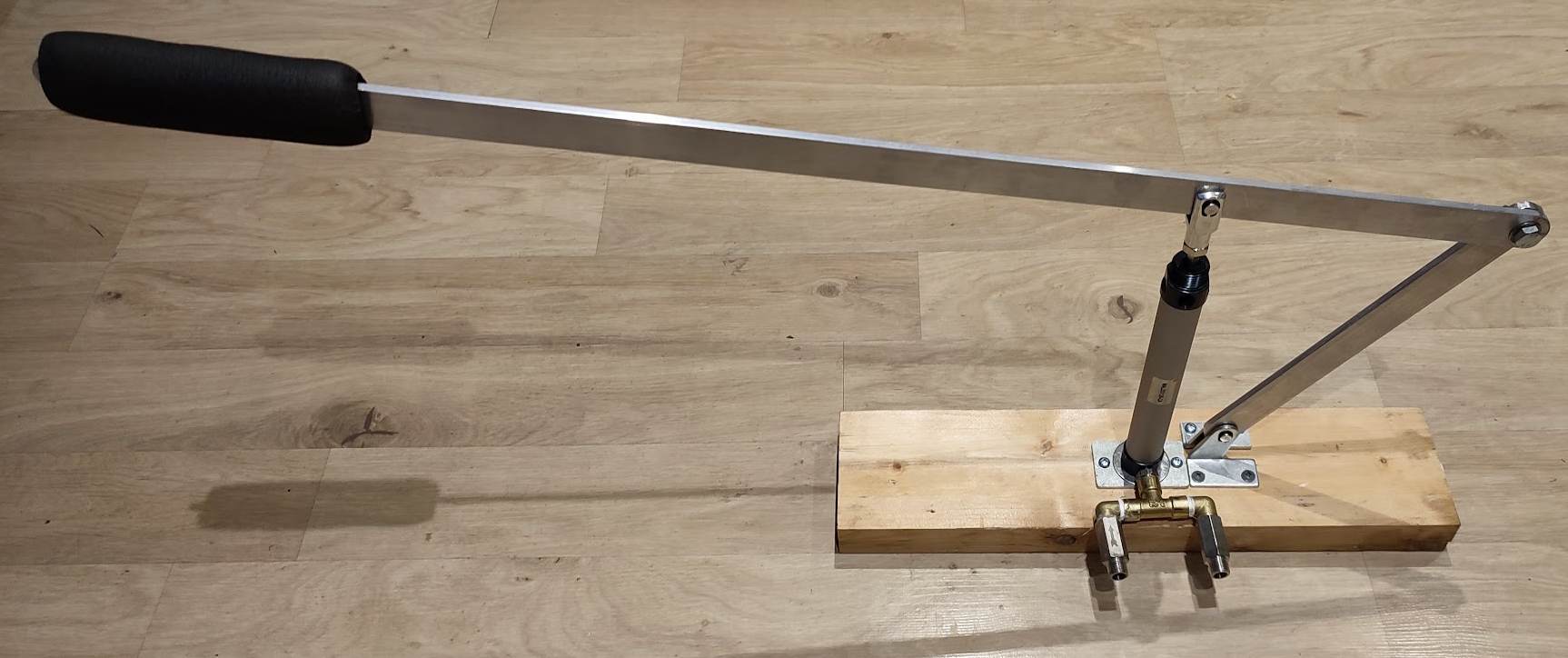 |
At this point consideration needed to be given to the handle. A 5 mm bar, edge on, is not particularly comfortable to use. One needs a softer, broader handle if the lever is to be used for extended periods. One solution, in the quick and cheap direction, is 10mm ID insulation tube that is widely used by heat pump installers, plumbers and solar thermal fitters. If you spot one of those instances some skip diving or face to face requests will yield more than enough offcuts which are essentially a waste material to them.
A second alternative is a short length of 25mm/1” broom handle. This can be sliced in half lengthways and the two halves put on either side of the aluminium bar. They would probably be best bolted into position, but taping them down with Gorilla tape or equivalent would be fast.
Thus many possibilities are open to the pump builder and this document will not dictate what should be done.
Having completed the Frances Anne vertical design attention moved to the Rolph style horizontal design. A base plank was found, cleaned up and then marked for the position of the two pivot brackets. It was proposed to make the bracket at the lower level with a couple of bits of angle iron, while the other bracket would be the angled one from Ali Express. The latter required a block to raise it by 60mm which was easy enough to acquire from the waste wood pile. That was secured to the board with a couple of screws and some Gorilla glue. The board centre line was continued up the block and onto the top. For this pump with just a single lever the pivot bearings can be aligned on the centre line, allowing 5mm for the thickness of the lever and 15 mm for the thickness of the cylinder base on the block.
This cylinder had also had a 1/8” BSP-1/4” BSP adapter fitted to the bottom port. However, the cylinder end had refused to unscrew in the way that the previous cylinder had. Thus the opposite end cap was removed along with the piston so that the swarf from the boring out to 6mm could be removed. With the boring done and cylinder carefully cleaned, the piston was replaced and the end cap screwed up.
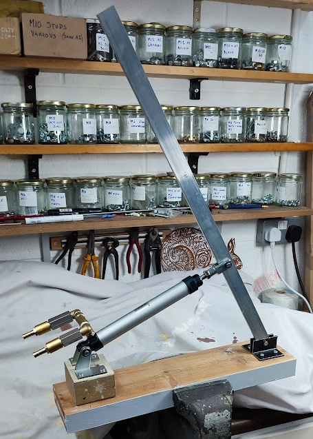 |
The pivot brackets secured the pump cylinder by using the not quite Clevis pin that was supplied with the bracket set. It is slightly long so the odd M8 washers were added to remove the wobble. A word of warning is appropriate here as one needs to decide whether the inlet/outlet port and associated plumbing should go above, below or to the side of the cylinder. Below looked better but there was not quite enough room for the plumbing so it had to be above.
Next the knuckle was screwed onto the shaft and locked. The two pivot bearings were made up from some angle iron and then clamped together to ensure that the bearing holes were drilled in alignment. The hold down screw holes did not need that treatment. The two items were screwed onto the base board with a 5mm gap for the lever. The main lever was then secured in place as before with an M8 bolt turned into a Clevis pin and the odd anti-rattle washer. The final step was to connect the knuckle jaws to the lever using the supplied not quite Clevis pin. Again some padding washers were useful.
Once that was done the final step was to complete the plumbing. With this design there is a small complication. That is the fact that as the pump is activated the barrel goes up and down. This means that solid fixed plumbing cannot be used and thus flexible inlet and outlet pipes are required. The initial ‘T’ arrangement used in the Frances Anne style pump will work well and just needs the addition of hose connectors beyond the non-return valves.
With those steps taken the job was as good as done except for the handle on the lever. Some options for that were discussed above and do not need repeating here.
The final section of this document will be devoted to the testing of the two pumps. Not being a pump engineer, a professional pipe testing agenda is not to hand, but as a boater one can suggest a few things that might be useful to know. Firstly, how much water does the pump deliver for (say) ten strokes? Secondly, how much water pressure can the pump achieve?
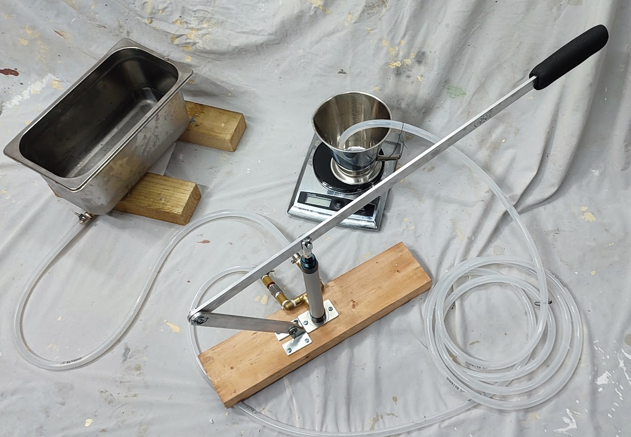 |
For the first test it was proposed that the hot well should be set up with its planned low level output fitted and then connected to the pump input side. After some initial pump strokes to prime the pump, it was proposed that the pump output should be connected to a suitable container mounted on a digital scale. The pump would then be activated for ten strokes and then the weight of water in the container weighed.
For the second test it is proposed that the outlet pipe should be led to the manifold of the mono-tube boiler. On that the whistle isolator would be closed, the engine supply globe valve would be closed, the drain plug should be fitted and the condensate overflow port be used for connection to the pump. With that set up there would be no outlets from the manifold, except to the pressure gauge. Thus it has been assumed that activating the pump would raise the pressure in the manifold which would be recorded by the gauge. As a minimum measure of success the pump should be able to work up to a pressure just beyond the red line on the gauge (90 psi). It is proposed that the mono-tube boiler will ultimately be hydro tested up to twice the operating pressure. However, at the time of writing the whole of the heat exchange coil is not fitted in the casing, nor is the rest of the inlet plumbing. Thus the proper hydro test will have wait until later.
With the first test equipment set up and water in the hot well all that was needed was to make a few pump strokes to prime the pump and fill the delivery tube. Unfortunately, pumping produced zero result and the pump would not prime. To solve this the cylinder was split and some water poured into the bottom casting. The cylinder was then replaced and a couple of strokes of the handle were made. This showed that there was a serious leak where the 1/8" BSP-1/4" BSP adaptor had been fitted. Once dismantled it was discovered that no PTFE or other sealant had been used. With that rectified, it was found that the pump would draw water and push it out to the receptacle. With that working the jug was emptied and the scale switched on. That refused to operate and signalled 'flat battery' presumably from having been left overnight in the cold garage.
The scale was swapped for a 'warm' one from the house and the test pumping began. The calculated volume of the cylinder (20mm Diameter, 125mm height) is 39.3cc. Tested for a single stroke the tube pulled up and deliverd 39g of water. Thus it was anticipated that the output from ten strokes of the pump would be about 390g of water since 1cc of water weighs 1g. The measured results were rather disappointing:
41g, 30g, 36g, 58g, 54g, 38g, 29g, 36g.
It was noted that there was a slight seepage from the elbow on the output side of the pipework but that was not large and was insufficient to account for the low quantities pumped. It was then decided to extend the test and try a different approach to pumping. This time the up (intake) stroke was done slowly and the down (output) fairly quickly. This produce quite different figures for ten strokes:
91g, 90g, 91g, 92g, 90g.
Whist this was rather better it was still less than 1/4" of the expected output. Clearly the pump must be drawing air in the intake stroke rather than filling the cylinder completely full. The possible culprits would seem to be leaky joints in the plumbing or perhaps the one way valve on the output not preventing air intake on the up stroke. This seems less likely than leaking pipes but the output pipe was filled with air and water so it might be possible.
Next the other pump was set up having corrected the same omission as on the first pump. Once again the pump refused to prime despite much effort. It is possible that the input non-return valve could be restricting the flow. Having a non return valve of similar design a substitution was made but this was ineffective. It was then realised that a solution might be to use the tee set up from the first pump as that had actually allow water to flow. Thus the first pump was raided and the second pump part dismantled.
Thus with the tee changed the Rolph style pump was happy to prime and then pump water. It was then decided to carry out the test and thus the kitchen scale and jug were set up as before. The measured results were as follows:
218g, 222g, 235g, 2330g, 228g, 240g, 242g, 235g, 260g, 257g.
It was noticed that as the test proceeded the delivery pipe was purged of air and the output improved. By way of a final test one round of ten strokes was carried out quickly, unlike the main test that had been slow. The quick pump series yielded 242g of water which suggested that speed of pumping was not that critical.
The tests would seem to suggest that the non return valves would probably be better if they were the traditional flap type. It was also clear that getting 1/4" BSP screwed joints to be waterproof is much more difficult than expected. Some research on that technique is clearly required. The less than expected performance appears to be down to the plumbing side which was not A1.
Two 'traditional' style flap based 1/2" BSP non return valves were acquired along with four 1/2" to 1/4" BSP adapters. The tee arrangement from the Rolph pump was removed and stripped down. The spring based non return valves were removed and the flap based valves substituted. The tired can of Stag jointing paste was re-vitalised with some solvent and appeared to make a difference to the joints. It is messy stuff and both hands and components were soon covered in dabs of it. Following advice from the Internet all the connections were re-made with more Stag paste and less PTFE. This appeared to give a better if messy result. Finally the Tee was re-attached to the Rolph pump and the pipes were re-attached as before.
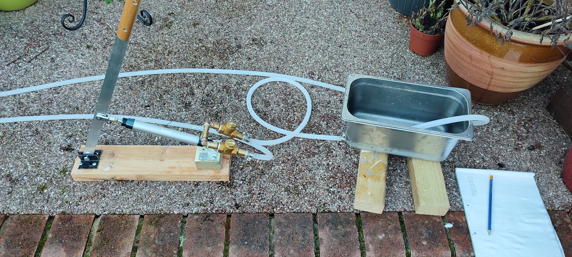 |
Once the hot well had been filled with water the test began. However, it seemed sensible to make sure that the delivery pipe from the pump was fully purged of air before starting. The pump primed with no trouble and the revised tee showed no sign of leaks. Interestingly each stroke of the pump felt as if it was pulling plenty of water.
With the outlet pipe filled, the test jug and scale were added and the tests began. It was quickly found that pumping too hard created a strong gush of water from the outlet pipe which proceed to rocket itself out of the jug and spread water everywhere. The test was re-started with less vigorous pumping and yielded the following result:
453g, 451g, 470g, 454g, 449g, 475g, 464g, 502g, 451g, 461g.
These results are somewhat perplexing as they seem to show that the pump is shifting more water than the cylinder can hold. That is, of course nonsense, so the test was re-run taking care to ensure that the scale was at zero before each round of pumping. One thing that the test clearly showed was that the new flap based one way valves provided no restriction on water intake and successfully prevent back flow.
Back in the office some quick calculations in a spreadsheet provided a possible answer to the odd figures. There was no magic, but there could well be inaccurate counting of the pump strokes plus a bit of run over from the end of the delivery tube. Dividing the figures by 12 then multiplying by 10 gives output figures that are within the logical range. By this stage, however, it seemed to be a waste of time expending more effort on this test. With the inlet and outlet pipes full of water with no air bubbles, a single stroke consistently produced 39g of water. The pump was obviously filling to capacity on each stroke. The tendency of the outlet pipe to 'jet away' also suggested that a fair degree of output pressure was being achieved. It was clearly time to set up the boiler manifold for the pump pressure test.
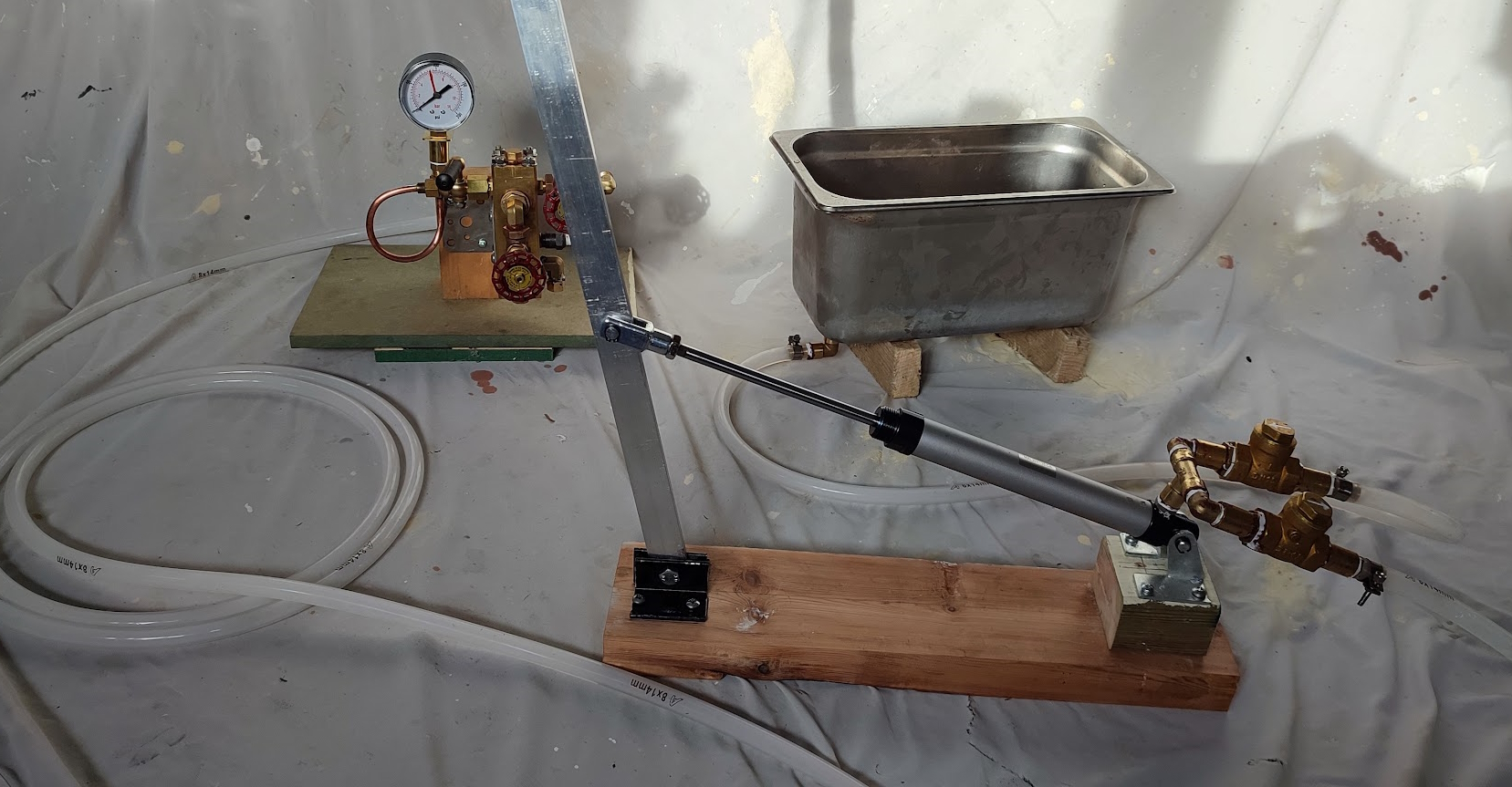
The manifold was removed from the casing and mounted in the vice where it was easy to examine every port. The safety valve was removed and replaced by a 3/8" BSP plug. The spark plug was found to be only finger tight so that was mounted properly with Stag and PTFE. The main steam inlet pipe was not tightly fitted which gave the opportunity to change it for a hose tail fitting. The steam outlet was securely fitted and all that was needed was to close the valve. Similarly the whistle outlet was secure and the isolating valve just needed to be closed. The pressure gauge piping was not quite up to scratch so that was re-made, leaving just the scale drain. That was designed to have a 3/8" BSP plug which again was only finger tight. That was secured with Stag and PTFE and the manifold was hopefully pressure tight and ready for the pump test. The remaining problem was how to set up the manifold with all the other bits and pieces so that the pump could be operated and the pressure gauge read.
The eventual solution was to screw the manifold support bracket to a short length of thick wood and then to screw a square of MDF to the bottom of the wood. The result was a fairly stable support that looked as if it would do for the test. With that done the hotwell was set up and then the flexible tubes were re-connected to the Rolf style pump. The jubilee clips were all tightened up rather more than before as the previous test had not involved much pressure whereas this test would involve significant pressure.
 |
The steam outlet valve was opened and then the pump was started. It primed quite quickly and began to send slugs of water down the rather long pipe to the manifold. A small pot had been placed under the steam outlet valve to catch water and to indicate that there was water up to the manifold. There was soon an overflow to the pot but at the same time it was spotted that there was water dribbling onto the floor. It was quickly discovered that the fixings for the manifold bracket to the manifold had been forgotten. They were 'lightly fixed' and had no sealing which meant that the layout needed to be dismantled and the issue addressed. It was not a big job but showed that every fixing should have been examined rather than assuming that all were tight.
With the fixings made water tight the whole set up was re-created. The flexible pipe was very securely fastened with the Jubilee clips tightened up as far as they would go. It was then time to set the pump in motion. Once water was back as far as the manifold the steam outlet valve was closed and the pressure test began.
What was surprising was how quickly the pressure rose and how little effort on the pump was required. That is not to say no effort was required but it was less than had been expected. The pressure gauge climbed towards the red line and then there was a 'pop' and the hose connector and the pipe on the pump parted company with a spectacular rush of water down the garage. The joint was re-assembled and the Jubilee clip moved closer to the end of the pipe which was higher up the shoulder of the hose tail fitting. The Jubilee clip was tightened down as far as it would go and then the test began again.
The pressure gauge climbed up to the red line (90 PSI) and just beyond but was quickly obscured by a fine fan of 'mist' which turned out to be the hose tail to pipe connection on the manifold leaking. With the pumping stopped pressure dropped back to about 45 PSI and then very slowly tailed off leaving everything in the vicinity wet.
It is probably safe to suggest that the pump is clearly good for 90-100 PSI* but in the current context more work is required to establish how to make hose tail connections tight for high pressures. A first idea is to go back to the Jubilee clip supplier and see if there are clips that are marginally smaller. If that is the case then it should be possible to squeeze the flexible pipe tighter and stop it moving or leaking. Perhaps in addition it would be worth seeking out instructions on how to make waterproof hose tail connections.
With that research done the hose tails were fattened up with some lengths of Gorilla Tape and then the joints re-made. The hot well was topped up and then the camera was placed handy for taking the high pressure reading photo. Pumping started and the pressure climbed easily up to the red line. Pumping continued and 100PS was reached and the camera was about to be picked up. However, there was a loud 'pop' and I was suddenly drenched from head to foot. Needless to say the pressure gauge reading fell like a stone. Next the two hose tails were examined and they appeared to be sound. Next, thinking about the direction of water that drenched me, the coil of hose in front of the manifold was examined. That was very clearly burst open and dribbling the remains of the water in the tube.
That was a disappointing event for several reasons. Firstly yet more water was added to the garage floor and secondly the hose was shown to be unsuitable for use on the pressure side of the feed water system. That was a bit of a blow as I had bought what seemed like enough for that system. A subsequent check on eBay of the vendor's site revealed that way down in the product specification was the comment "Unsuitable for pressurized systems". I had not noticed that when purchasing the product. This issue raises a small problem for the Rolph design in which the cylinder moves with each stroke. Thus there is a need for a flexible hose for a short part of the system. Back to the internet for some more research! At this point it seemed sensible to suggest that enough testing has been done to prove that these pumps would work well with the mono-tube boiler under construction.
Overall the use of these cylinders to make a quick and inexpensive hand pump seems to be justified.
*Postscript: I have had a private communication from Rolph to say that his team have used these cylinders up to 200PSI without problems but the rubber/silicon piston seal is not really good for long term high pressure use.