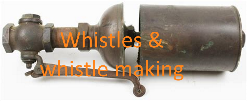
Source: https://www.liveauctioneers.com/ (Now Sold)
“Wheezeless Whistles”
by Bob Bramson January 2020 Edition
This article first appeared in the Society of Model and Experimental Engineers Journal Volume 18, No 3, in May 2010. Bob updated the article in 2020 for Model Engineer and has kindly allowed us to reproduce it here. The focus is mainly on locomotive builders, but everything he has to say is relevant to those of us in the steam boat arena.
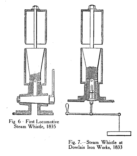
To most people, the appeal of the steam locomotive derives from its sight, its smells and its sounds. The steam whistle is perhaps the most evocative of locomotive sounds and with its single or multiple tones its discharge will turn heads and thrill most everyone within its audible range. It may be of interest to readers that the steam whistle’s origin was in 1833, an idea by one Thomas Turner who designed a steam road locomotive. The first working whistle is attributed to William Stephens, a workman at the Dowlais Iron Works in South Wales also in that year. Its use soon became standard on all steam locomotives, its primary role is of course, to provide an audible warning or signal, however, the sound it emits is always capable of arousing the human emotions. In models this is often far from the case. Perhaps due to lack of understanding of the principles involved, the performance of the average miniature whistle is beset with wheeziness, overblowing or dull and lifeless tones.
 |
Just before the December 2009 Model Engineer Exhibition, I was asked to demonstrate whistles on the SM&EE stand using my electric test boiler to provide the steam supply. This request came right out of the blue and I agreed to make some whistles for demonstration at the show. It just so happens that I needed to solve the problem of “Wheezing Whistles” several years previously when I completed my 5” gauge B1 “Roedeer” and was surprised at the amount of interest that was shown at the exhibition and the number of people who reported difficulties in making these instruments work successfully. This together with recent developments has prompted me to rewrite this article which I hope will be of interest to devotees of miniature steam engineering.
Let’s start with a bit of simple physics. The model engineer seeks to scale full size and in so doing reaps certain benefits and also certain disbenefits. When considering the construction of miniature vacuum ejectors, injectors, turbines and whistles the question of steam velocity is high on the agenda. It is second nature to thermodynamicists to know how the velocity of steam varies against pressure, however, this fact may not be well appreciated by people in other walks of life, so might I explain in very simple terms that the velocity of saturated steam escaping into air at zero pressure is, naturally, zero. Raising the pressure to just 10 psi, the steam has attained approximately the speed of sound and at around 40 psi, twice the speed of sound. As the pressure rises further the rate of change of velocity reduces significantly such that at the pressure ranges encountered on full size locomotives it is almost constant. It should be rather obvious that the model engineer needs to consider how to deal with this phenomenon when making miniatures which depend on steam flows over the range of pressures which normally apply, say 30 to 120 psi. The other fact that applies and is critical in any steam driven entity is condensation. What’s all this got to do with a simple whistle you ask? Well, just about everything!
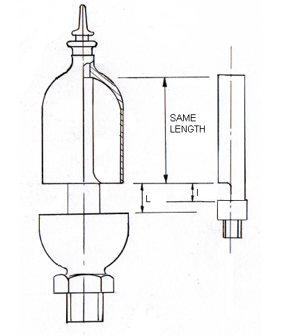
If you consider a full size locomotive whistle, the steam slot height is around 2” in length shown as L in Fig.1 a). This is to enable it to function properly at the working pressure and its associated steam velocity. As the pressure reduces, the steam slot height must also reduce to reflect the reduction in steam velocity. The miniature version shown in Fig.1 b) has to have a slot length l reflecting the steam velocity associated with the lower pressures involved. A mouth blown whistle has a slot height of about 3/16”. Table 1 shows the relationship of slot length l in inches against pressure in psi. It is thus most important that this is incorporated in the design and construction of miniature whistles.
 |
One of my friends once told me that hot weather assured a “good whistle day” and cold weather a “good injector day.” Well I don’t altogether agree with this since with deference to “physics,” the grand master, it is possible to make the best of the situation using its principles. I am truly amazed that so many whistles which you see appended to miniature steam driven models are made of unbelievably thick yellow metal. These personify the ultimate in steam condensing apparatus! There is no hope for such monstrosities. Many people have said to me that their whistles work perfectly well on air but were useless on steam. Hardly surprising, as the steam simply condenses and the velocity energy dissipates instantly upon contact with the great bulk of cold metal. So, having incorporated the right slot length, the next thing to do to ensure a “Wheezeless Whistle” is to reduce the effect of condensation. This is achieved by using very thin sections for all the parts of the whistle, and yes, also the steam supply pipe work that feeds it. In full size, the whistle is mounted directly on the boiler or other hot surface, however, on a model locomotive it has of necessity to be mounted somewhere away from a hot source. One remedy that a revered model engineer friend of mine employed was to use superheated steam to work the chime whistle on his little loco “Petrolea.” This certainly did work, although I believe he found that the supply tubing tended to burn out due to the intermittent steam flows. All you need to do is to take the steam from the driest source in the boiler and if the whistle is remote from the control valve, feed it with steam through well lagged pipes. In the past, I have used electrical heat shrink in two layers which seemed to work reasonably well once the initial condensation had been cleared, more on this subject later. The bore of the valve and steam pipe should be comparatively large such that the pressure drop at the whistle is minimised.
|
Working Pressure - psi. 50 |
Slot Length - inches 0.4 |
|---|---|
| 80 | 0.6 |
| 100 | 0.75 |
| 120 | 0.875 |
For the whistle itself, the dimensions shown in Fig.2 are offered as a working design for either a 5” or 7¼” gauge locomotive and the sound will resemble a typical LNER bell whistle. Some important points are:-
• The ratio of the tube diameter to the slot length should be between 1:1 and 1.5:1.
• The pitch of the note is proportional to the length of the tube from the contact tip of the aperture to the inside of the cap.
• The volume of sound depends on the energy you put into it and is influenced by the diameter of the tube. A 3/4” diameter tube will generate all the sound volume you need in 7¼” gauge.
• The contact edge of the steam slot should be perpendicular to the flow of steam, sharply finished but not tapered.
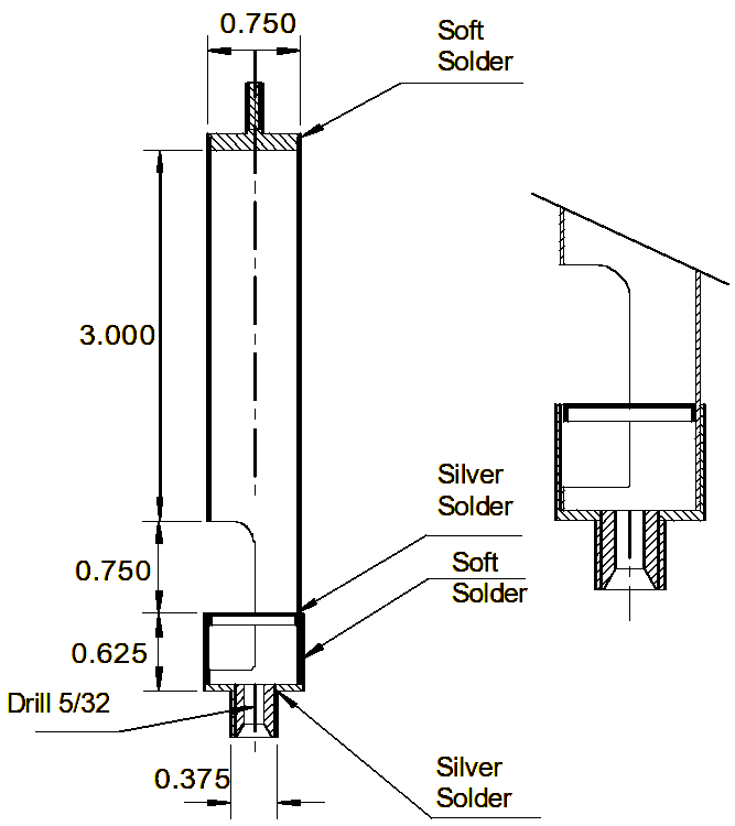 |
It will be noted that the deflector plug is the same diameter as the internal diameter of the tube and thus the steam slot gap is the same as its thickness. Many people resort to gaps only 0.005”. This is not only unnecessary but is undesirable as most of the velocity energy is destroyed in the throttling process at the slot. This remedy reduces the pressure and velocity, however, since it raises the steam temperature it tends to counter the condensation loss which suits the small apertures traditionally employed although it also results in a dull lifeless tone. When the steam hits the deflector plug, it tends to condense, so machine out as much of the redundant material as possible.
It should also be apparent that a whistle is in fact a musical instrument and its timbre is materially affected by the hardness of the whistle bell. Since my wife is a bell ringer, as no doubt are some model engineers or their ‘nearest and dearests,’ I am aware that nearly all church and hand bells are made out of tin rich copper alloys to give them their tonal qualities. This might be considered overkill for a little whistle, however to obtain good results, hard brass tube is quite satisfactory. Dear old LBSC used to specify “Treblet” tube i.e. tubes that had been drawn three times to impart greater hardness and stiffness. I have not seen this material advertised since the early sixties but I have been fortunate in obtaining supplies of something similar from a friend of mine in Taiwan. The essential requirement is that the tubes are thin. A ½” diameter tube should be no thicker than 0.015” (28 Bwg) and 3/4" to 1”; 0.020” (25 Bwg).
This type of whistle is best mounted in a warm draught free environment, say between the front end of the frames on a loco. Support for the tube is provided by a threaded extension shown at the top of Fig.2 at the cap and via a light support stay to secure it to some adjacent structure. The steam pipe end should be left free. It is not desirable to clamp the whistle as this will prevent it from resonating and promote still more condensation. Any condensate must be allowed to drain out of the voice slot which should be set at a slight angle to facilitate this.
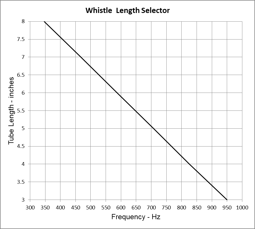
Fans of different railway companies will no doubt wish to install a prototypically sounding whistle. The frequency of a whistle depends on the effective length of the tube. This, over the range that model engineers are concerned is a linear relationship and it is thus a comparatively simple matter to tune to a particular musical note. The graph and formula in Fig.3 can be used to approximate the tube length to suit a desired frequency. To achieve best results it is desirable to tune a new whistle against a frequency source (I use a music centre keyboard) this being achieved using an air tight plunger in an over length tube in the manner of a swanee kazoo.
 |
Some tube lengths to suit various popular whistle tones are as follows:
GWR warning (thin body) ; 3 7/8”
GWR Signal (wide body) ; 4 7/16”
SR Hooter; 4½”
Stanier LMS Hooter – 185 Hz F#; 10”
GNR / LNER High Pitch; 3”
When Sir Nigel Gresley was designing his P2 2-8-2 locomotives the story goes that he visited the 15” gauge Romney, Hythe and Dymchurch Railway in Kent which had fitted Crosby chime whistles to their 4-8-2s and was very impressed with the sound. He had also travelled in the USA where chime whistles were a standard fitting. He readily decreed that the new locomotives should be fitted with voices having similar tones. Thus was born their use on British mainline railways. The A4 chime or more correctly, Tri-Tone, comprised C(4) F(4) and A(5) although other tones were used.
LNER Chime; C 523.28 Hz; 6.53” F 698.48 Hz; 5.08” A830.64 Hz; 3.99”
BR Chime (Crosby); F# 370 Hz; 7.8” C# 554.4Hz; 6.27” A 880.00Hz; 3.58”
Chime whistles for miniatures can either be made with individual pipes or segmented within one large diameter pipe. For miniature locomotives up to 7¼” gauge, it is easier to make the whistle with individual pipes since the condensation losses will be less. For larger locomotives of 10¼” gauge and the bigger traction engines, the segmented monotube design is more appropriate. One thing to appreciate is that large whistles do use a fair amount of steam which will be apparent if used on the smaller models.
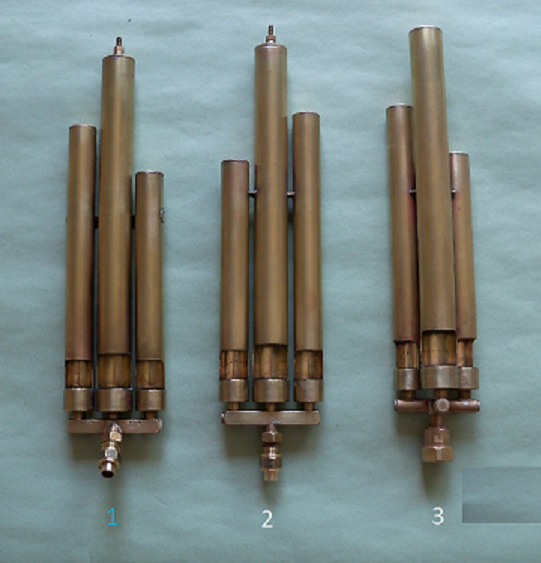 |
I am pleased to commend an excellent article by D A Gulliver-Brown on “Making Chime Whistles” which appeared in Model Engineer (20th June 1969) wherein comprehensive detailed instructions were published. Photo 1 shows a practical design for three note A4 style chime whistles similar to his design. It should be noted that the diameters of the steam entry holes into the whistle chambers are different. This is to balance out the sound levels of the whistle pipes such that no particular note dominates. For 5/8” diameter pipes, the short tube’s base should be drilled No.36, the medium, No.32 and the long one, No.30.
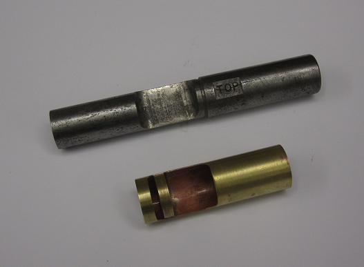
Since a reasonably skilled model engineer should be able to produce a perfectly good whistle I don’t feel it necessary to include full instructions save to suggest that a jig is a useful adjunct to form the voice slot in the thin section tubing illustrated in Photo 2.
 |
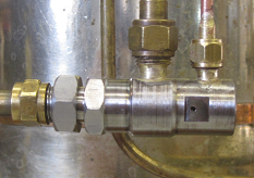
Earlier on I mentioned about condensation losses in long pipes that feed steam to whistles. As a member of the SM&EE, for me the experimental side of model engineering has always played a big part in the enjoyment of our hobby. When I set out to build the boiler for my 1/8 scale LNER C1 Atlantic, I decided to feed the steam directly from the dome via an internal steam pipe to the front of the boiler. At the time I must confess that I had no idea how the system could be operated remotely from the cab. Recently, on a longish train journey, I borrowed a pen and paper from my wife and started sketching. The result was a steam operated relay valve designed to fit under the front of the smokebox saddle which has a conveniently flat base from which to mount it. The idea was that when it is desired to sound the whistle, a normal turret type valve would pass ‘signal’ steam approximately 36” to the relay valve Photo 3 to pressurise a small piston This in turn tips a ball valve off its seat to work the whistle – simples!
When I returned home, I just had to make a prototype and see if it would work. I selected grade 303 stainless steel for all the working components since the valve would always have water in it when in storage and anyway, stainless works much better for steam valve seats. Photo 3 shows the finished valve ready for testing. I duly connected it up to my electric test boiler and gave it a try. Imagine my consternation when after it was activated it wouldn’t stop! Visions of aggravated neighbours flashed through my mind then I quickly realised that the steam had condensed in the signal pipe and locked the system open hydraulically. The solution was achieved by simply releasing one of the union nuts on the remote actuating valve and hey presto, the whistle ceased. Phew, no irate neighbours! Not only did it do the trick but by passing the escape of steam from the actuating pipe, this could readily provide a show of steam from a dummy whistle. On the test rig, the valve works perfectly but as ever, it needs to be proved on the loco under service conditions which is about a couple of years away all being well. The leading dimensions for this valve are shown in Fig.4.
 |
For readers with iPhones or PCs you can view a short video of a test run with the relay valve on YouTube https://www.youtube.com/watch?v=heUtkGuGFOY . This shows the performance of the whistle at 30, 50 and 100 psi. The poor response at low pressure should be capable of improvement following a small modification.
I feel sure having made many whistles to the above designs this article includes all the necessary ingredients for making a whistle which will sound clearly and with good audible tone first time, every time.
Bob Bramson
January 2020
Next: Seeking a Whistle