The Canoe
Sirius 6 was built by John Emmett and C McCormack from a Kayel Canadian kit using the stitch and glue method in which the hull pieces are initially held together with 'stitches' of copper wire. Those are then followed by short lengths of 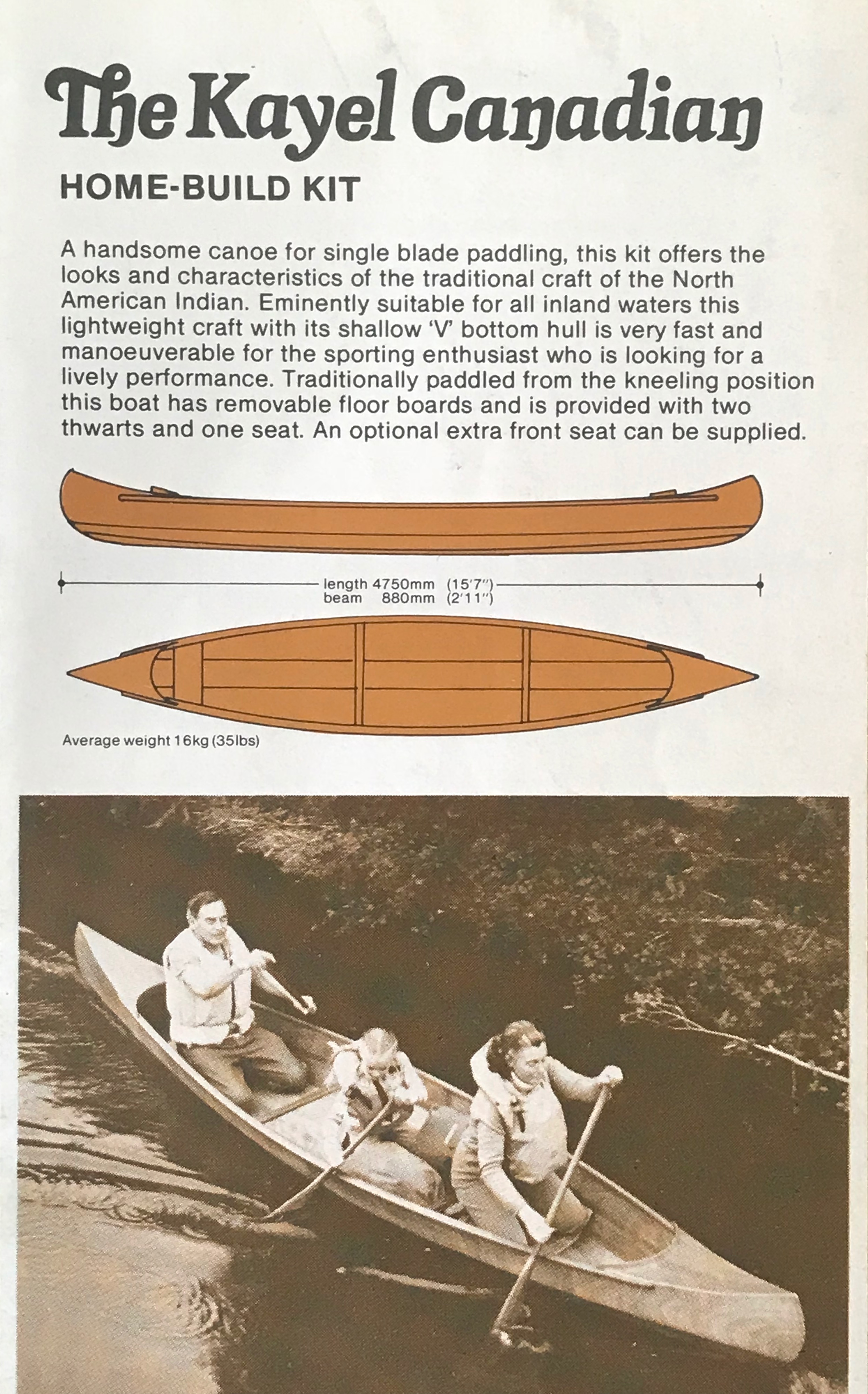 fibreglass tape stuck down with resin over the joins. Once that has set the copper stiches can be removed and the taping completed along the length of the seams.
The method produces a very strong and surprisingly light structure. A canoe of this type is ideal for transporting on a car roof rack as well as being small and light enough to store from ceiling pulleys in the typical domestic garage. The canoe route is a very inexpensive route into steamboating as the Sirius kit cost £125 in 1979, equivalent to approximately £703 in 2022 prices. Such canoes are still available as for example the Fyne Boats Sassafras 16, which is around £1400 and rather more sophisticated than Sirius 6, or Boatkits 16ft Touring canoe which comes from the EU (1,200 Euros).
Sirius 6 was built from essentially six strips of ply, comprising 3 on each side with butt joints. Most of the modern canoe kits seem to be based on the idea of clinker ply with many more planks. Why this change has occurred is not obvious but it may be an attempt to create a more traditional appearance as can be seen in the Fairlight 406 canoe.
The initial steam fit out comprised a Clarkson compound and small Water Tube Boiler. However, in 1980 the boat was re-fitted with a Stuart Turner No. 1 single and a mono-tube boiler. Details of both are given below.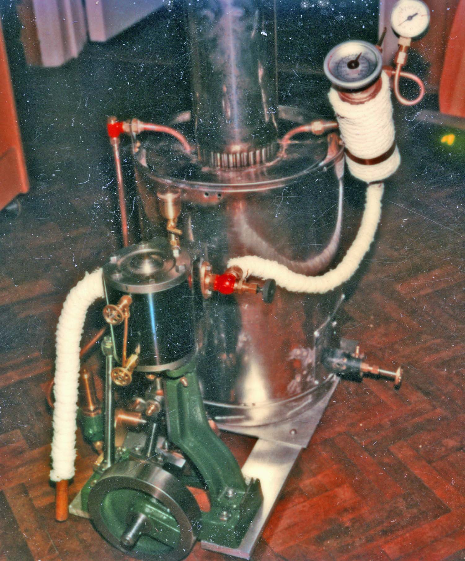 The boiler was fired by propane gas.
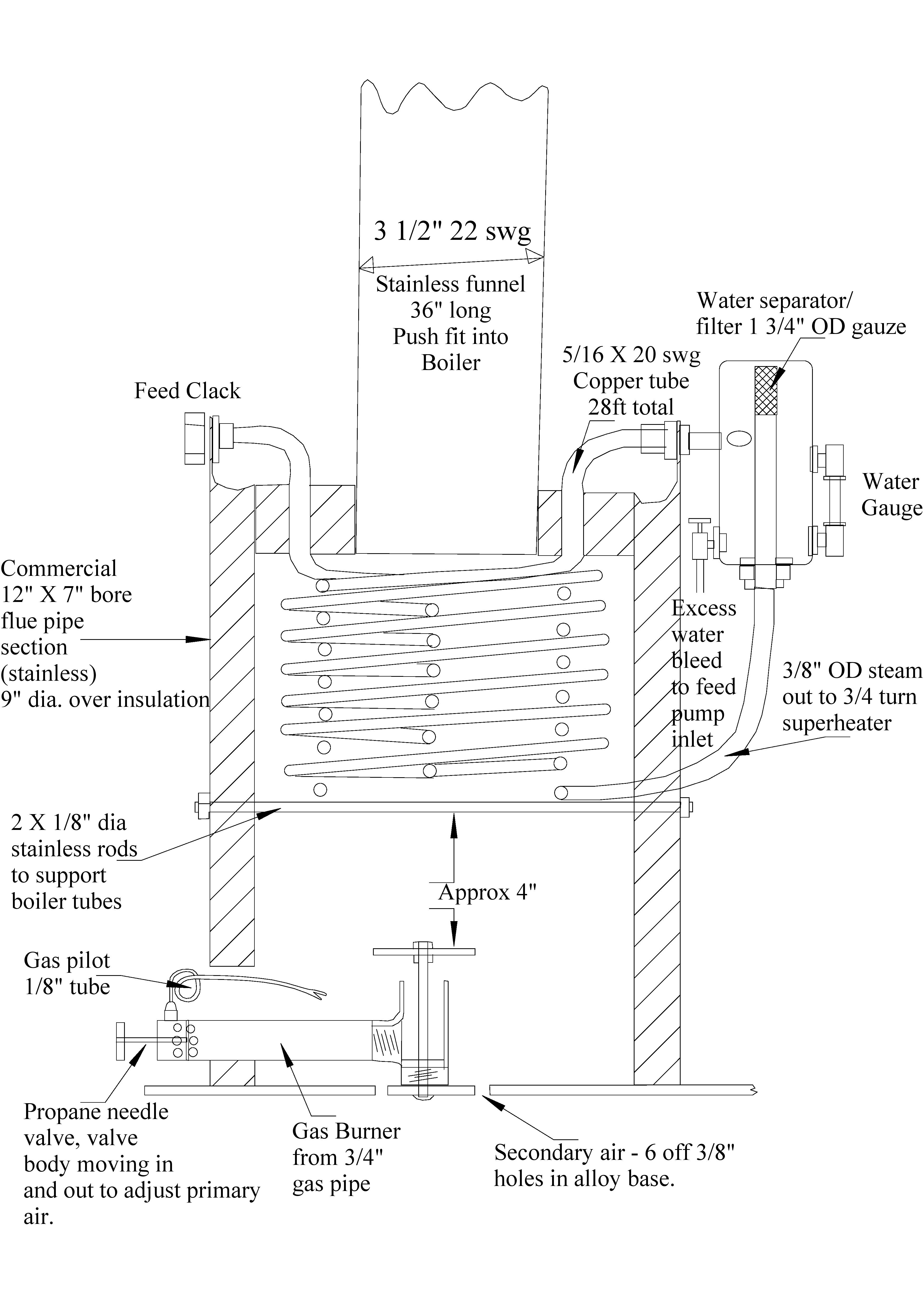
It can be seen from the drawing below that the mono-tube design used follows all the conventions that are found in the boilers reported in the SBA's Funnel magazine and elsewhere. Feed water enters the coil at the top where furnace gasses are cooling and progresses down towards the hottest part of the fire.
The coil, which by then may be carrying mostly steam, then goes back to the top of the boiler and exits to a water separator. The latter has a drain down to the hot well and also a water gauge to allow the user to assess how much has collected in the separator. The de-wetted steam then exits via a short (3/4 circuit) superheater coil to the engine.
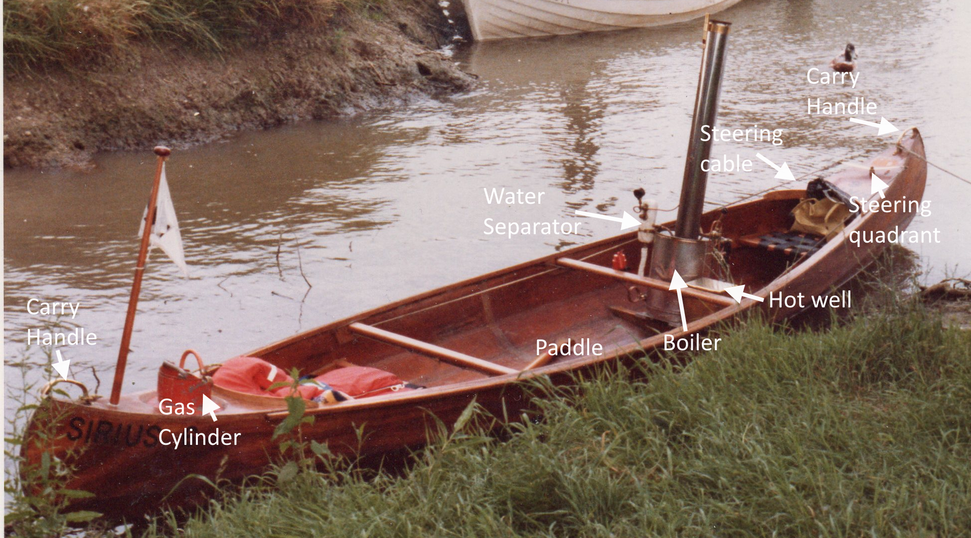
The earlier iteration of the plant as shown in the photo to the left has just two readouts for the user. The top of the water separator has a thermometer to show steam temperature, and also a pressure gauge. There is no flue gas temperature gauge, but being gas fired the heat output would be steady so that information would probably not be required. A pipe from the water separator also fed the whistle that was mounted at the top of the chimney facing forward. The gas cylinder was mounted in a vented stowage area in the bow.
The installation also incuded a small brass hot well on the port side. Initial use of the system was with 'pure' water to avoid scale blowing through to the engine. 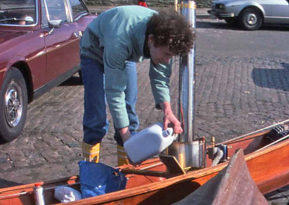 However, with the water separator in the system scale cannot blow through to the engine, but will gather in the hot well. Using 'pure' water avoids even that happening. (Picture below - Topping up the hot well). Associated with the hot well there was a condenser pipe running along the keel and back.
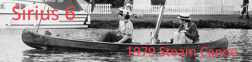
The boat managed a good turn of speed as is shown in the photo below. To achieve that the engine was connected to a 10" x 15" bronze 3 blader. Bit too big, but Norris’ of Isleworth had it just sitting there, second hand and shiny. The prop shaft was 9/16”. The first engine/shaft coupling was a cheap alloy Picador which was sold in tool shops. The rubber element of this smoked despite the low power, because of the cyclic oscillation from the light discwheel on the Stuart No 1. A more rigid mild steel two pin coupling was fine; 1/4” pins spaced 1 1/4”.
Steering was by means of two cables, one on each side of the boat to a quadrant mounted on the rudder shaft. (See two photos below)
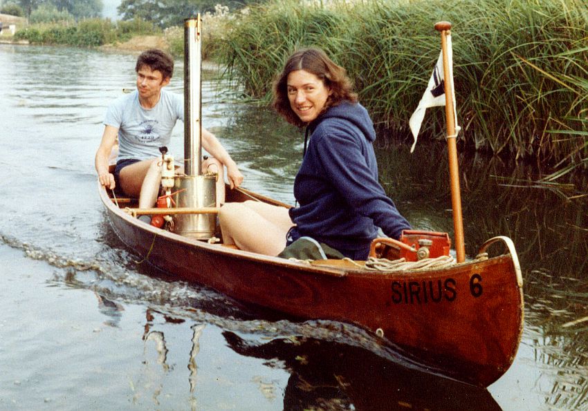
Note how the 'Skipper' is holding the two steering cables in the photo above.