The Boiler in Snipe
In designing a mono-tube boiler for a canoe one naturally is very conscious of the fact that canoes are at the 'pencil' shape end of the boat design spectrum. That means that they are very tender, or tippy, if one does not keep the weight low down in the boat. A good reminder of this is to watch paddle boarders who all too often seem to capsize given that they are standing on a narrow floating platform with a high centre of gravity.
The obvious solution is to develop a design in which the mono-tube coil is horizontal rather than vertical. That also throws up the problem of the risk of having a very long boiler so that having the coil running out and back seems the obvious solution. The concept that seems to be emerging is not dissimilar to the long box like boiler casing of the many water tube boilers to be seen in the SBA fleet though with very different technology under the cover. That is probably no bad thing as mono-tube boiler users seem to be considered rather eccentric by many in the SBA who do not understand the technology.
The first step was the development of the coils for which it was felt that two inter-woven coils joined at one end would provide sufficient length. These were made on a 10cm (4") wooden former. The two coils were just short of 16 turns each with 8mm Cunifer brake pipe. Thus each of the coils required (circumference X 16 = 65.3cm X 16) = 1,045.6cm (34.3ft) of pipe. The surface area of this, according to the CAD drawing, is 251,139.4 sq mm, which is abour 0.25 sq M or 2.7sq ft. for each coil length.
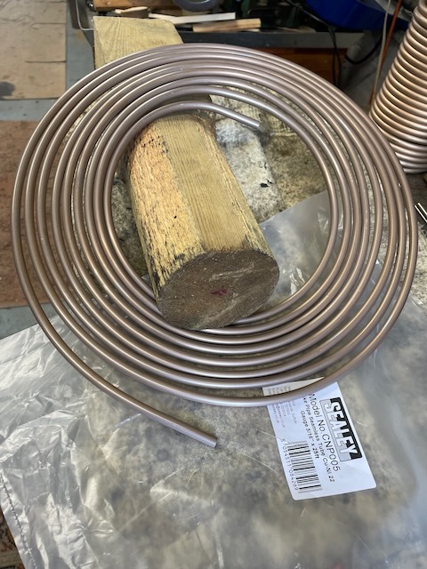
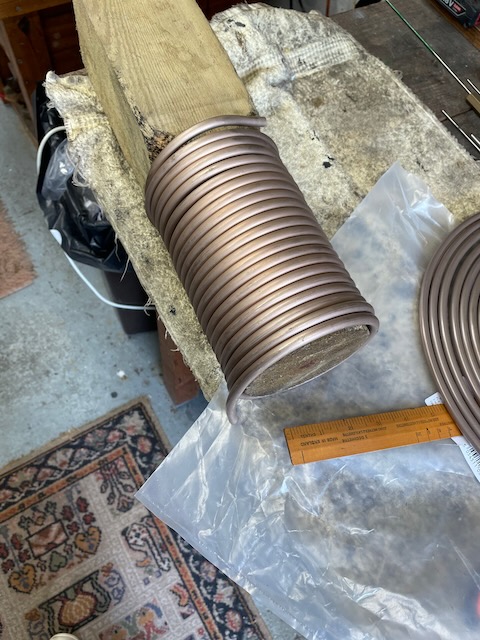
There are, of course, several ways to develop a new boiler format which include jumping in with the hardware or, for those with rather less confidence, working it all out on CAD first. Below is an initial concept view of the paired coils.
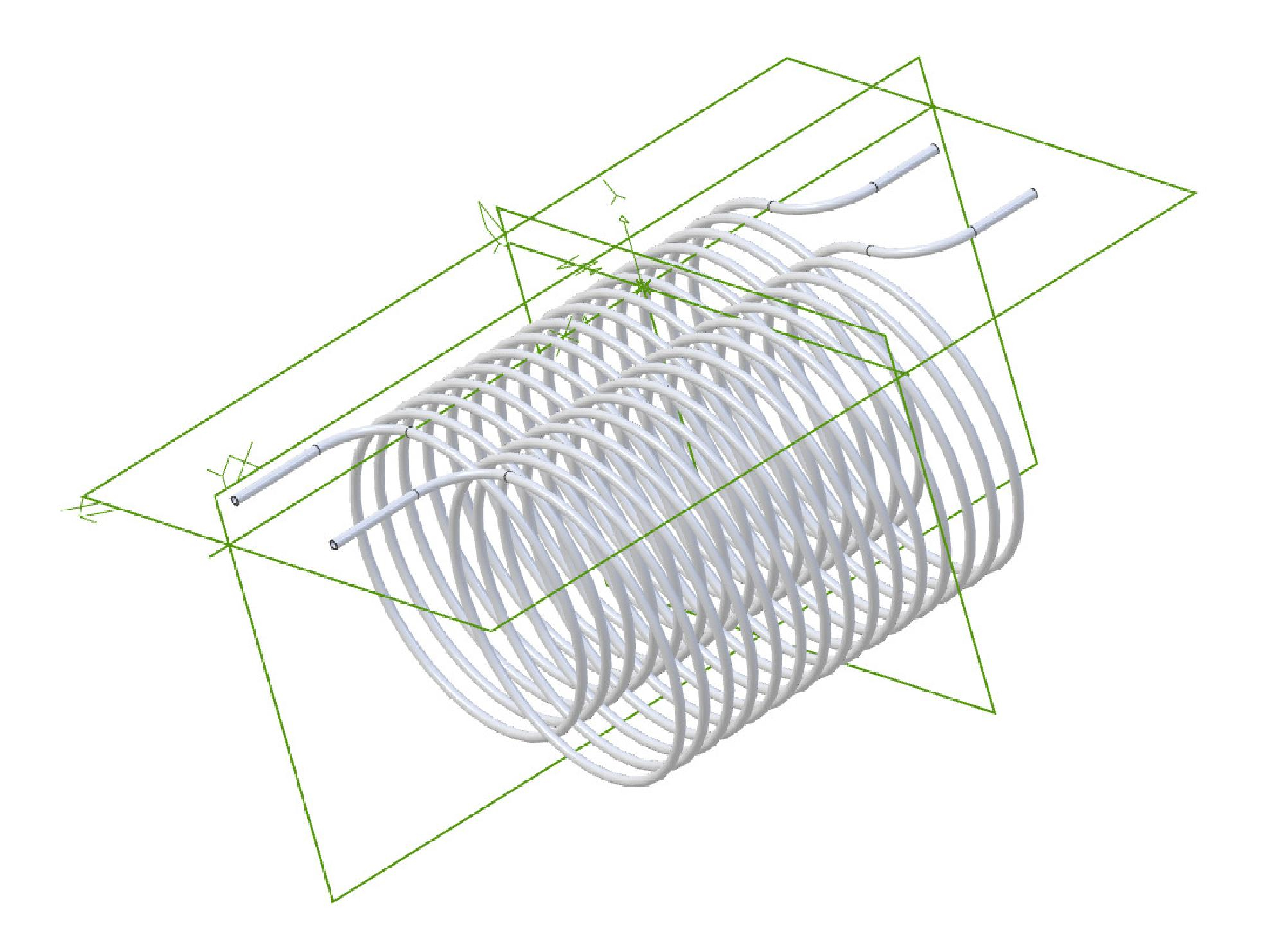
The CAD drawing immediately shows one problem which is the joining of the two coils. In the drawing both coils are wound in the same direction. However, if they were to be wound in opposite directions the 'tails' would face each other without the need to add bends. That would facilitate the use of a straight connector.
The length of the interwoven coils provides the length of the 'box' which will form the boiler casing. The degree of meshing of the two coils will also provide limits for the width of the casing. However, to both those dimensions one needs to add the thickness of the insulation batts that will be used to keep the heat in and the user safe from burns. As a minimum 25mm would seem sensible, but different materials offer different degrees of insulation.
Having identified that the coils will sit in a rectangular box attention needs to go next to the space for the fire. There is a Rule of Thumb often quoted in the SBA that a combustion space of 15cm (6") vertical space is required for a reliable fire. This can be used to work out the position of the grate and then an arbitrary 50mm could be allowed for the accumulation of ash beneath it. Thus adding up all the bits, (coil diameter, fire space and ash area) one comes to (10+15+5=30cm) roughly 30 cm height, 20cm or so wide (2 coils) and for the coils length when intermeshed (15 coils X 8mm X 2 = 24 plus a bit for manoeuvrer) is about 30-32 cm.
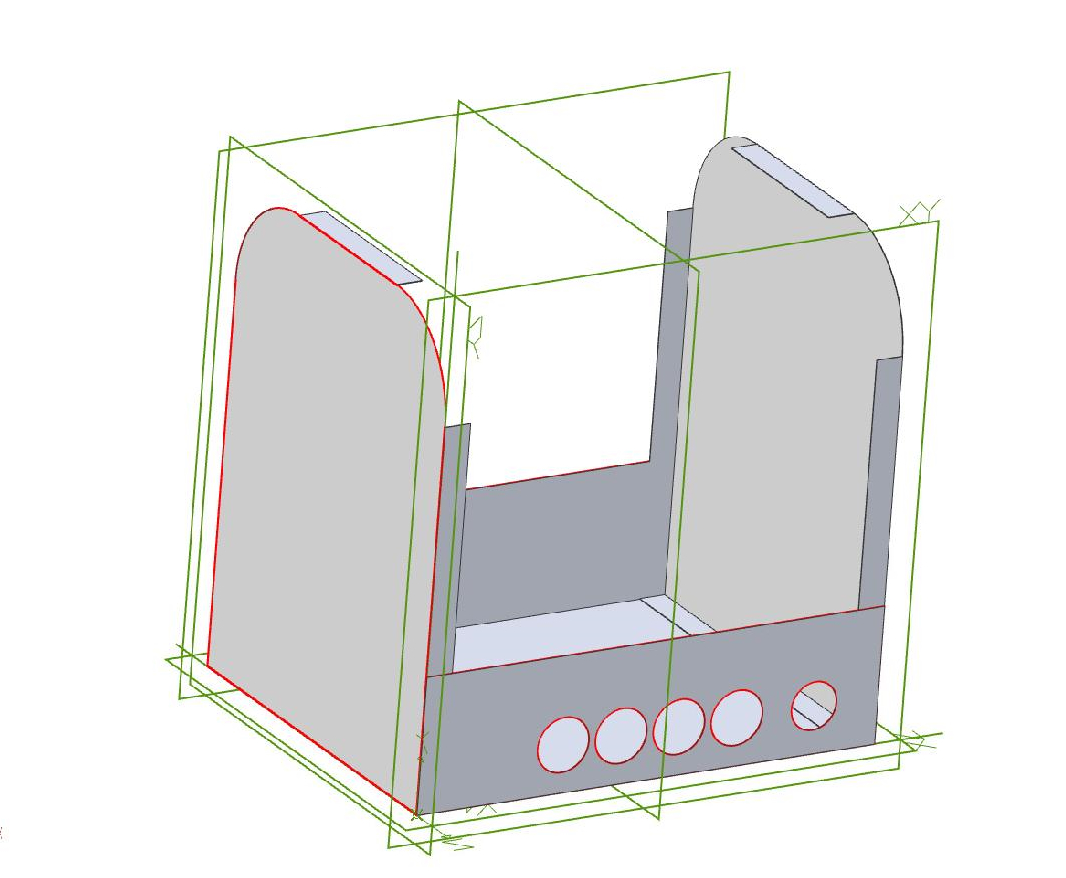 However, there are other fixed size limitations too, as the minimum fire door size in launch applications is about 125mm x 100 mm and, with solid fuels, space for stoking must be provided around the boiler to allow human size firing tools to be used. This is a particular problem in small canoes or launches where the user has to reach over the engine in order to fire, as well as needing visibility into the fire bed. Traditionally the firebox door would be at the narrow end of the casing facing the engine. In a canoe that is completely out of the question due to space limitations. The alternative is to have the firebox door at the side of the casing. Given that the sides of the casing need to be removable for tube cleaning it was a short leap to deciding that the sides of the casing should be hinged and become the fire doors which could be operated from either side.
Obviously a damper would be required so a series of holes covered by a sliding plate seemed simple and effective.
The funnel would sit on the top panel which would include a stub onto which the removable funnel could be easily fitted. The only question that remained was whether the side panels should just cover the flat side or be extended with a curve to meet up with the top plate. The latter seemed the simplest to construct and use so that is what was done.
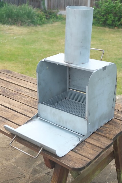
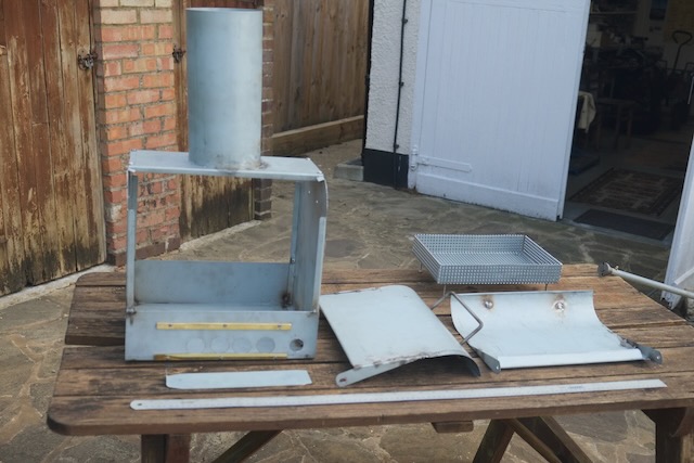
A number of other decisons were required such as the depth of the doors. Should they be full length or just from the fire bed level upwards? How should the hinge be arranged; a piano style hinge or pivot hinges? Should the door on the damper side of the box not cover the damper, thus needing longer 'legs' on the hinge? Another question was to do with keeping the firebox doors closed. The options were either to have over centre clip that would 'lock down' the doors or something simpler like a bent over tab locating in a slot. In the end the latter approach wa adopted as is shown in the photo below.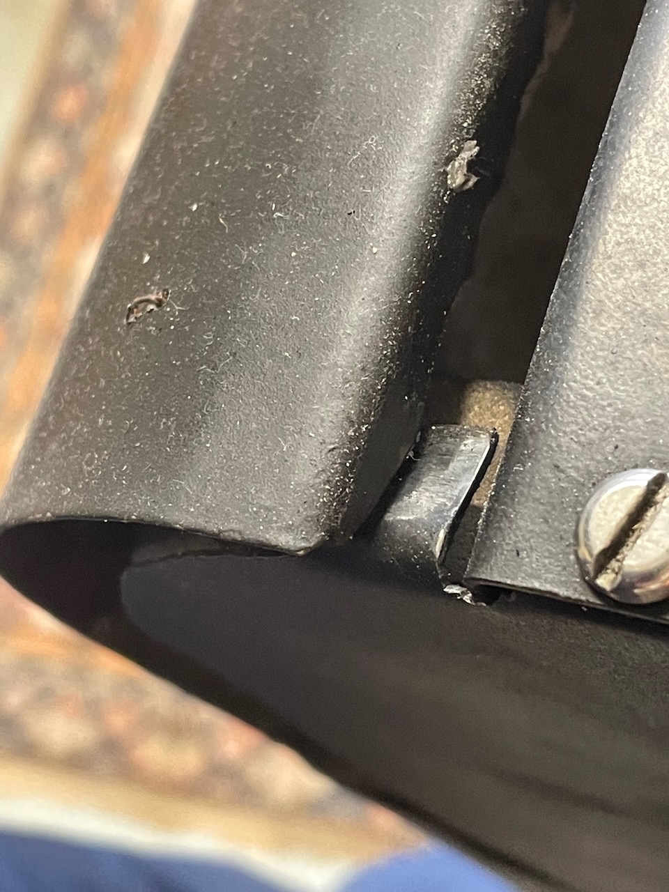
The final decisons on those questions are shown in the pictures above. The pictures also include the final design of 'fire basket'. In traditional water tube boiler casings the grate would be set up to rest on some kind of support attached to the sides of the casing with the ash pan beneath. For wood firing the amount of ash generated in an afternoon's steaming is very small which rather suggests that a removable ash pan is unnecessary weight and complexity. Why not just allow the ash to fall to the bottom of the casing and use a basket arrangement to hold the fire?
Traditional boilers tend to use heavy cast iron fire bars but with wood firing that is probably not necessary and something lighter ought to suffice. The initial design (shown below) was for 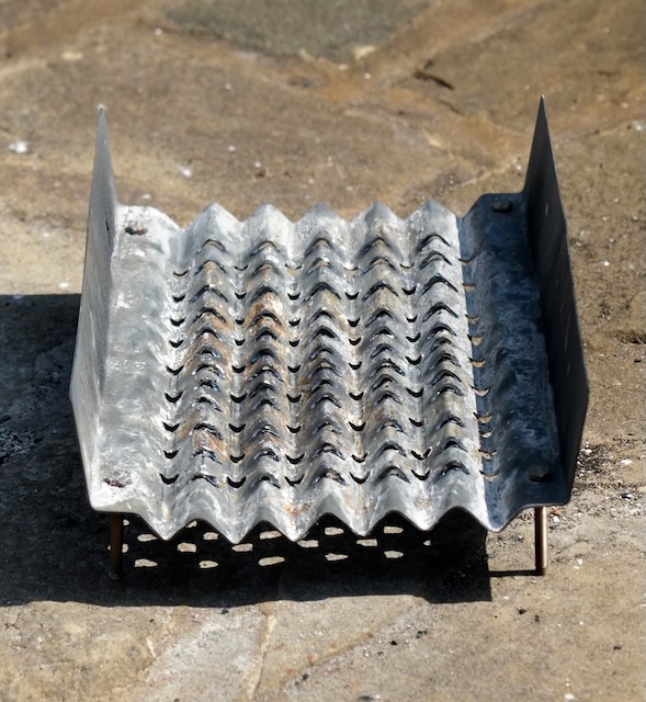 a drilled and corrugated sheet with four machine screws as legs to hold it up. This worked satisfactorily but it was felt that perhaps a grate with four raised sides would be better at keeping the fire off the insulation. Thus some perforated sheet metal was obtained and bent up into a basket, but retaining the four machine screw 'legs'.
Another factor in the dimensions calculation was the size of the proposed re-cycled wood logs. Typically a supermarket compressed wood waste log is 32-35cm long so the grate needs to be long enough to hold a couple of these logs.
The next thing to consider, once the fuel type and size has been established, is that it will be necessary to introduce approximately 14 times that mass of air to the fuel. With the short funnels that steam launches use use it is necessary to design the boiler air passages as efficiently as possible in order to maximize the available draught. That involves reducing as far as practical the acceleration of the air from ash pan entry to funnel exit. The key to that is the adjustment of the cross section according to the temperature along the route. It should be borne in mind that the gasses expand perhaps 5 times from inlet to fire box, then contract through the tubes to issue at twice the inlet volume from the funnel top.
For example, burning one gram of fuel per second (3.6kg per hour), 14 litres of air must also pass through the boiler every second. Thus a clear ashpan inlet passage of 140 sq cm will force the cold air to flow at a metre per second. In order to keep acceleration to the minimum therefore, cross sections of 700 sq cm in the firebox and 280 sq cms at the funnel will be needed. This yields approximately 7 inches as the internal funnel diameter. A metre per second may be an ambitious target, but 4 metres per second is definitely too much to expect for natural draft.
Taking all these factors into account the final size of the 'box' was 279mm wide by 355mm tall and 356mm long.
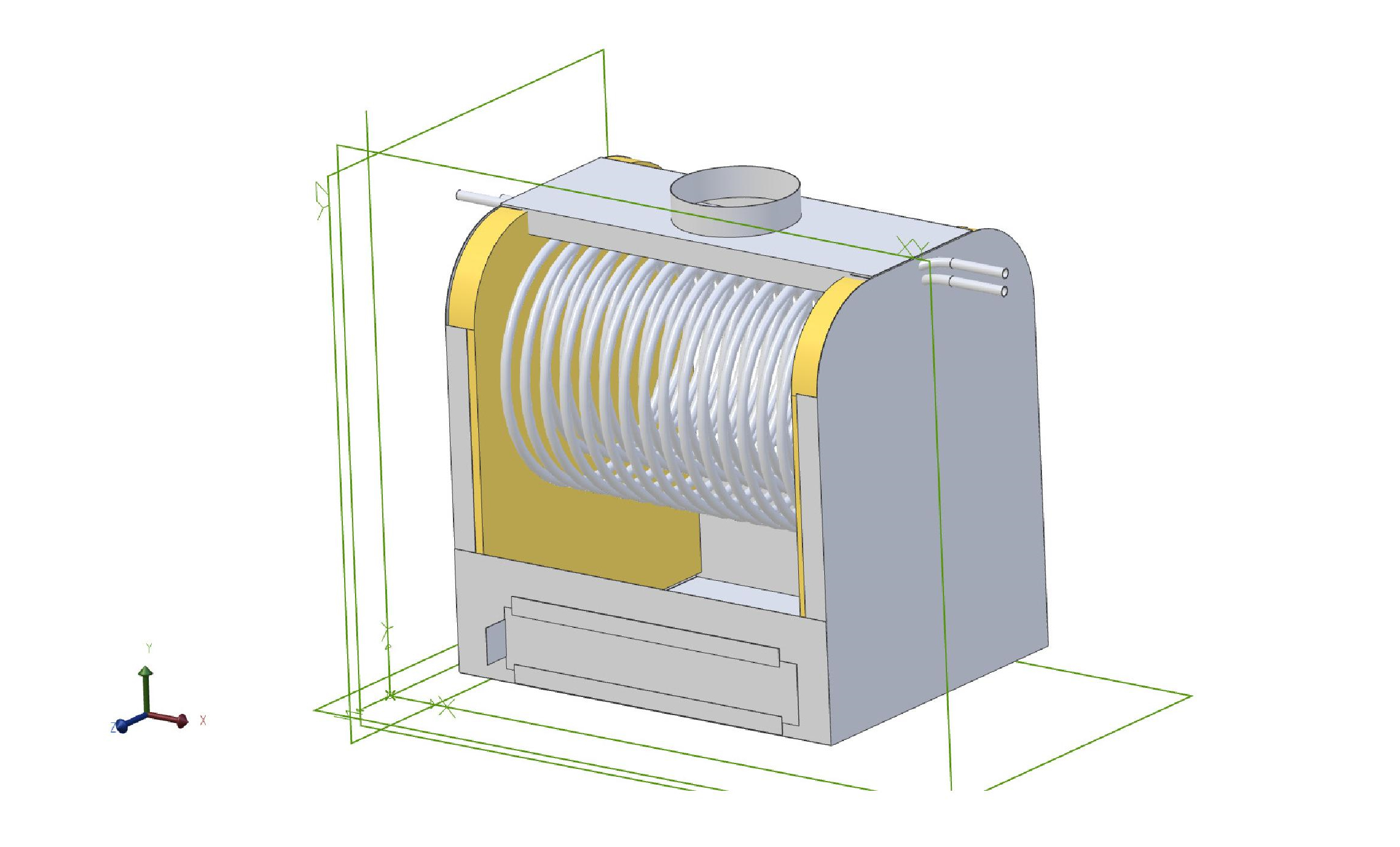
A small 'gap' in the thinking that has been made explicit so far is how the coils are to be supported. That turned out to be a very simple problem to solve. All that was required was a 6mm stainless rod tapped M6 at each end. The inner ends of the tapping have a nut and washer and then the outer end which pokes through a hole the casing has another washer and a domed nut. This solution is useful as it strengthens the box with a couple of 'stays' and yet is simple enough to remove if the coils need to come out.
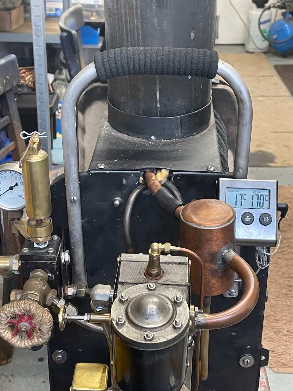
How this turned out in the actual boiler is shown in the photo below which clearly shows the stays on which the coils are resting. The photo also shows how the door on the damper side is arranged over the damper. It also shows that the coils at the front are in fact joined outside the casing rather than inside. At the other, engine end, of the casing the output side of the coil goes to a 'distribution manifold' and the inlet end goes down to the feed pump.
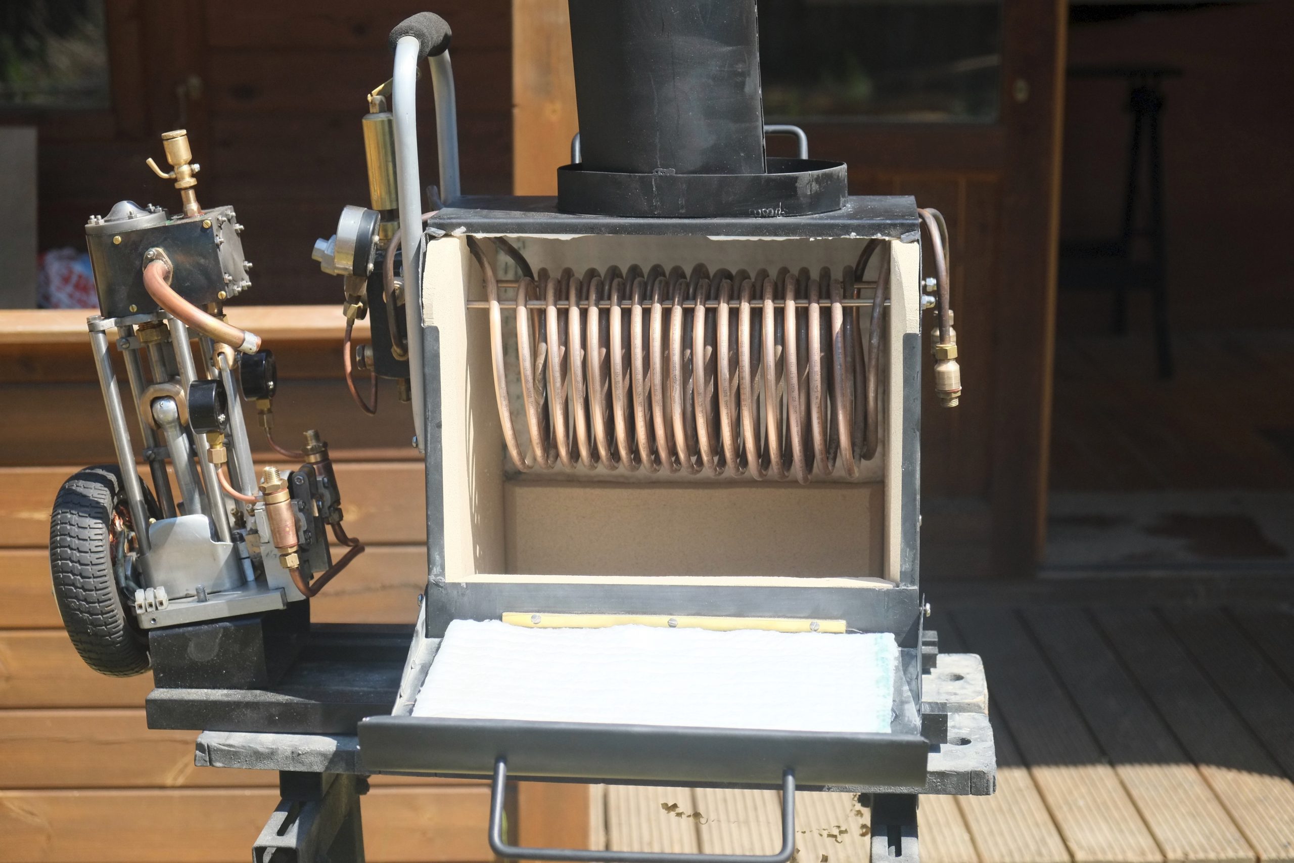
Another notable feature of this photo is the lifting handle at the stern end of the casing. An important element of most canoe based steam plant is that it is designed to be removable. After a day's steaming the boiler will have been extinguished but will by no means be cold. Thus the question is how should it be removed from the boat? The choice would seem to be handles of some sort either installed on the sides or at the end. However, the 'fire door' sides already have handles but those are designed for opening the doors not for lifting. Therefore a substantial handle on the rear face of the casing makes sense. In some ways a second one on the front would have made sense to balance the load, but would have been unappealing aesthetically. The joined coils at the front can act in lieu of a handle for the initial lift off the fixings and then the main handle should be sufficient for the remainder of the transfer.
The final element of the boiler relates to the ancilliaries. The key items under this heading are the steam distribution manifold and the feedwater pump. Details of these items will not be provided here but rather in the section of the site dealing with Ancilliaries and Controls. A preview of those items and the associated engine are to be had in the photo below.