The Propeller
27 October 2022
Following further work with Gerr's propeller handbook, serendipity leapt forth from eBay in the form of a two blade bronze (probably) propeller rated 13" diameter and 11" in pitch. Always one to fit into the traditions of the locale, I took the 'Cardi' approach and offered the minimum that ebay would permit. With the bid made I went back to looking at the huge range of 7.5" propellors that are available and tried to find one of a decent pitch. Many days later eBay sent me a note to point out that I had won the auction and that I ought to pay up. So I became the proud owner of a rather nice prop for £20 plus postage. It is obviously not in the first flush of youth but then neither am I and, unlike me, it did not have that many scrapes and dinks to record the passage of time. (See pictures below)
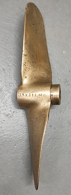
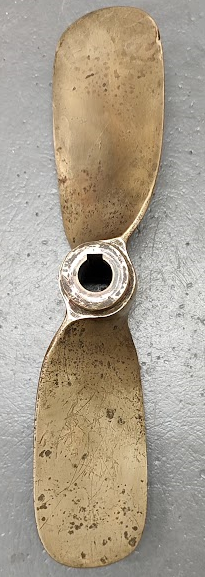
The next step is to see how a propeller of this size would fit and whether it might be sensible to knock it down to (say) 10 X 11. An examination of the hull design for the Fairlight has shown that the deep vee shape of the transom could in fact be reduced and flattened giving more space for the propeller. However, 'more' is an imprecise term and the result would be a skeg of around 8 inches (203 mm) assuming that the original skeg design is used. That would leave the propeller projecting below the skeg. However, that might not be a problem since the propeller is two bladed meaning that when coming up to launching ramps one could stop it in a horizontal position and it would not hit the ground. The same sort of thing would apply to launching, but it would mean no warming up of the engine on the slip unless there was a dog clutch between the prop shaft and the engine.
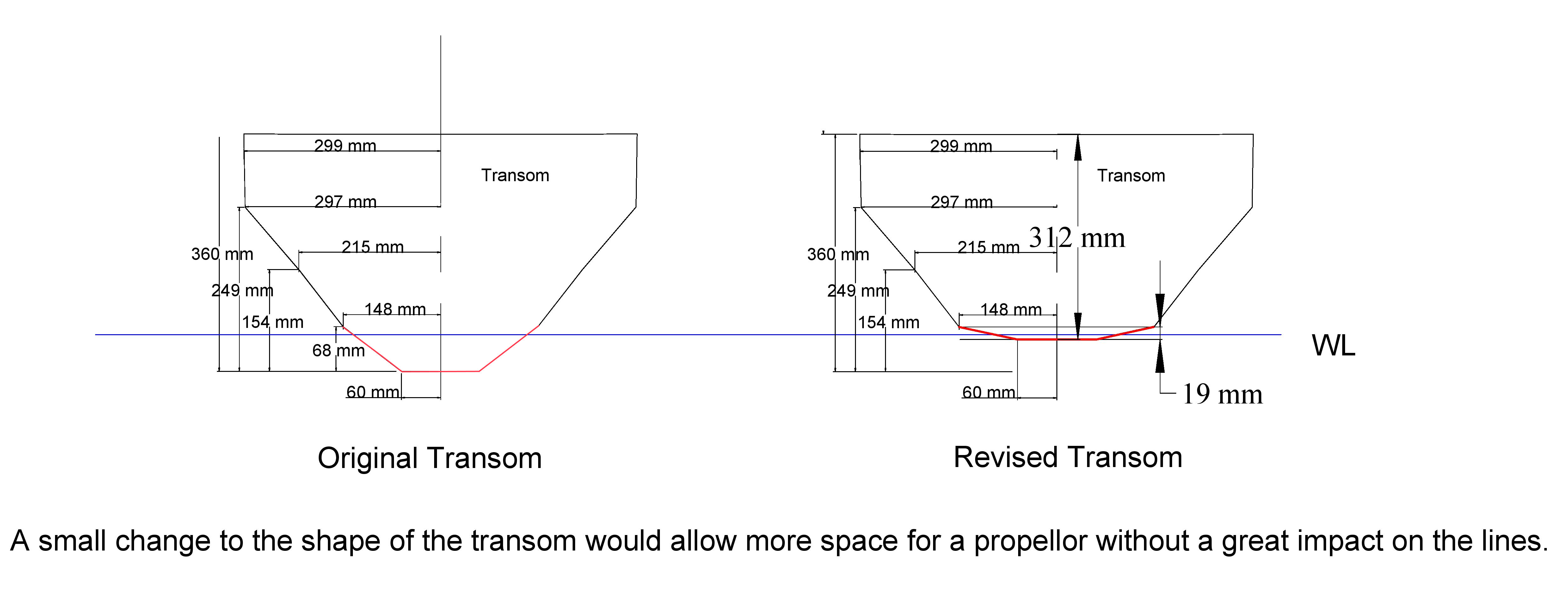
Making use of this change the profile would be as follows: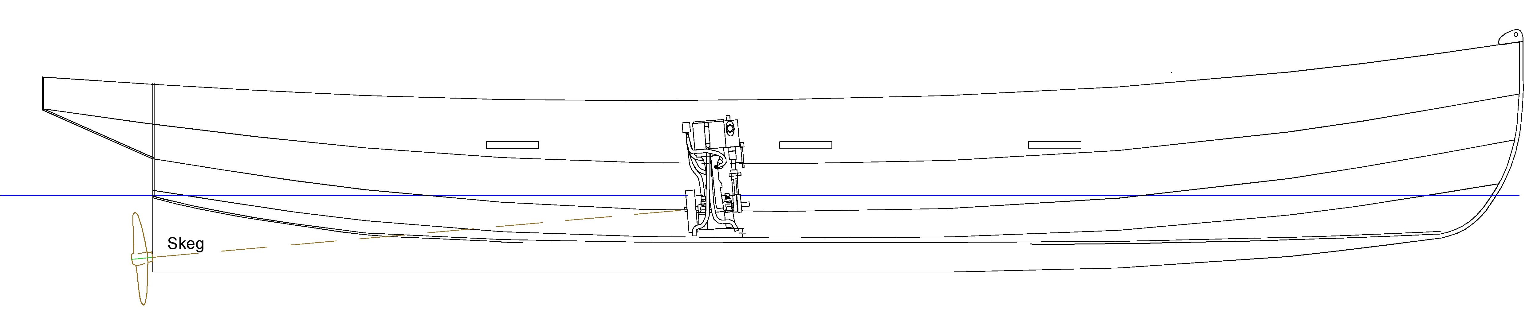
Several assumptions have been made with this layout. Firstly, the top of the propeller has been set below the water line rather than higher up on the grounds that a propeller that sucks air is not very efficient (See cavitation). The associated assumption is that the allocation of the weight of the plant will be such that the boat will trim correctly even when the engineer sits next to the engine. Thus the bottom of the transom should remain just at water level. Another assumption is that the propeller needs to be located beyond the transom to avoid vibration. Two bladed propellers cause more vibration than three or four baded propellers, but there is the problem of vibration caused when a propellor is sited too close to the hull. The SBA has a rule of thumb for that and suggests that propellers should be at least 2" (50 mm) below the hull. Gerr, as ever, has a rule for this which is that the tip clearance should be at least 15% of the propeller diameter with 2" being the very minimum. In this instance it seemed sensible to effectively move the propeller 'outboard' and thus avoid the issue.
Placing the propeller in this position does raise a problem of where to mount the rudder. The original design has the rudder mounted on the transom in a traditional manner. However, doing that would require a very large cut out to accommodate the propeller. Thus it might make sense to mount the rudder further aft with the shaft and bearing going through the counter (122 mm from the stern). That will cause a knock on impact in that the counter is very lightly specified and will need strengthening to support the rudder mechanism. However, the hole in the deck and underside of the counter can be abandoned as they were intended for mounting an electric outboard which will not be used. Thus some extra rigidity will be obtained.
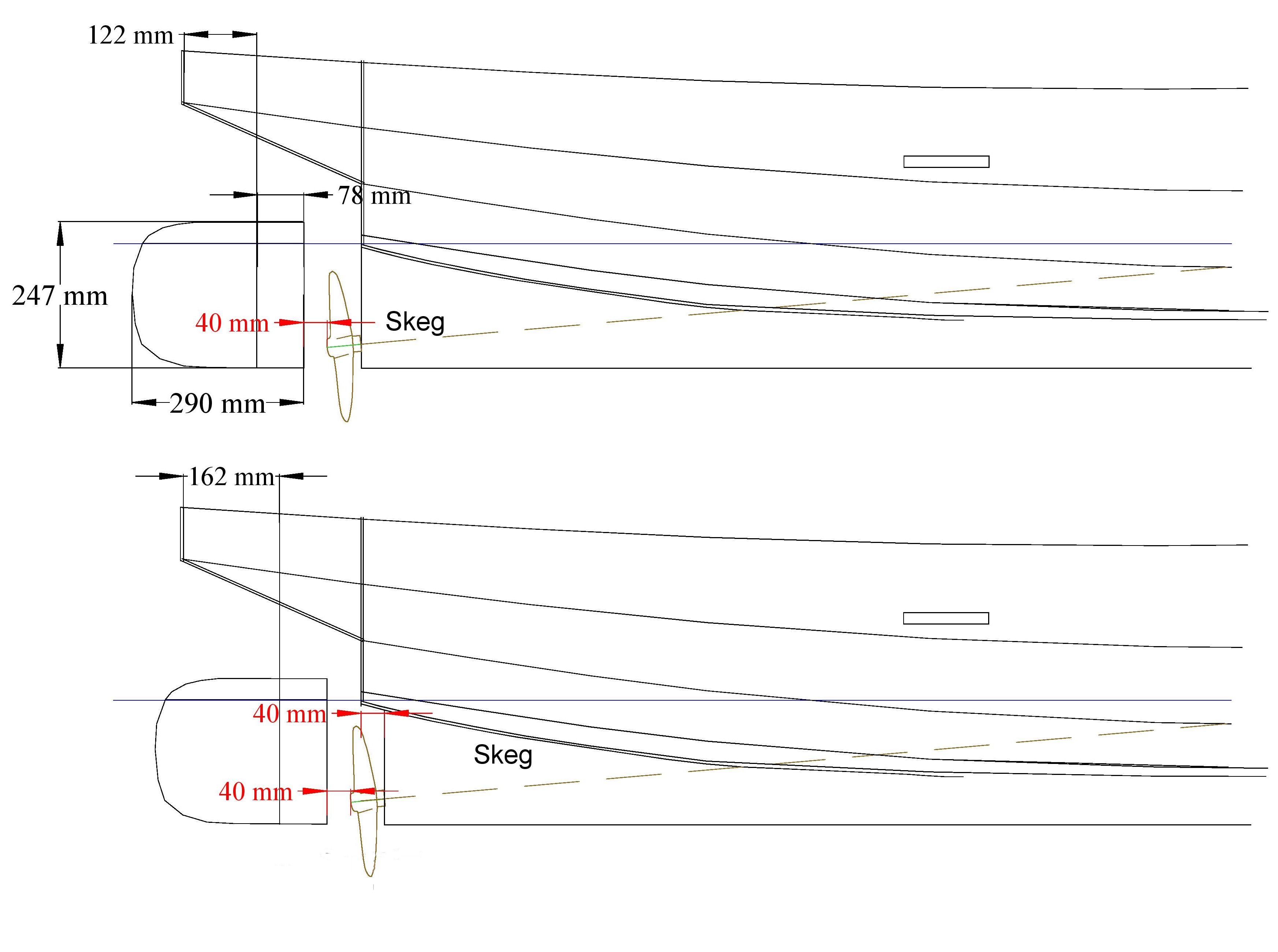
A question that is not answered in Gerr's Handbook is the size of rudder that would be sensible. However the original plans come with a rudder design so it seemed sensible to pick up the underwater area of that rudder. To it was added a cosmetic piece which might actually have some use if the boat runs with the stern down. It was also thought advantageous to have the rudder balanced to some degree. It would seem that there is not general agreement about that but 30% is an oft quoted figure. Given that the rudder is drawn as 290 mm 'long' it was felt that perhaps 78 mm looked 'about right' whereas the 30% figure of 87 mm did not. Next comes the issue of where to put it and, as was mentioned earlier, hanging it on the transom is not possible.
Gerr usefully recommends that the rudder should be at least 15% of the propeller diameter away from the propeller. With a 254 mm (10") propeller that is about 40 mm. Thus in the first drawing the propeller is set at that distance and that means the rudder shaft will be 122 mm from the stern. Next it was realised that since the propeller shaft will slope, the propeller will not be aligned vertically. It might, therefore be possible to cut away the skeg and move the propeller back a little. After some juggling it seemed as if a 40mm reduction in the rear edge of the skeg would meet the various 'rules'. This is illustrated in the lower picture above. The advantage of this change is that it moves the rudder shaft to 162 mm from the stern and more into the centre of the counter.
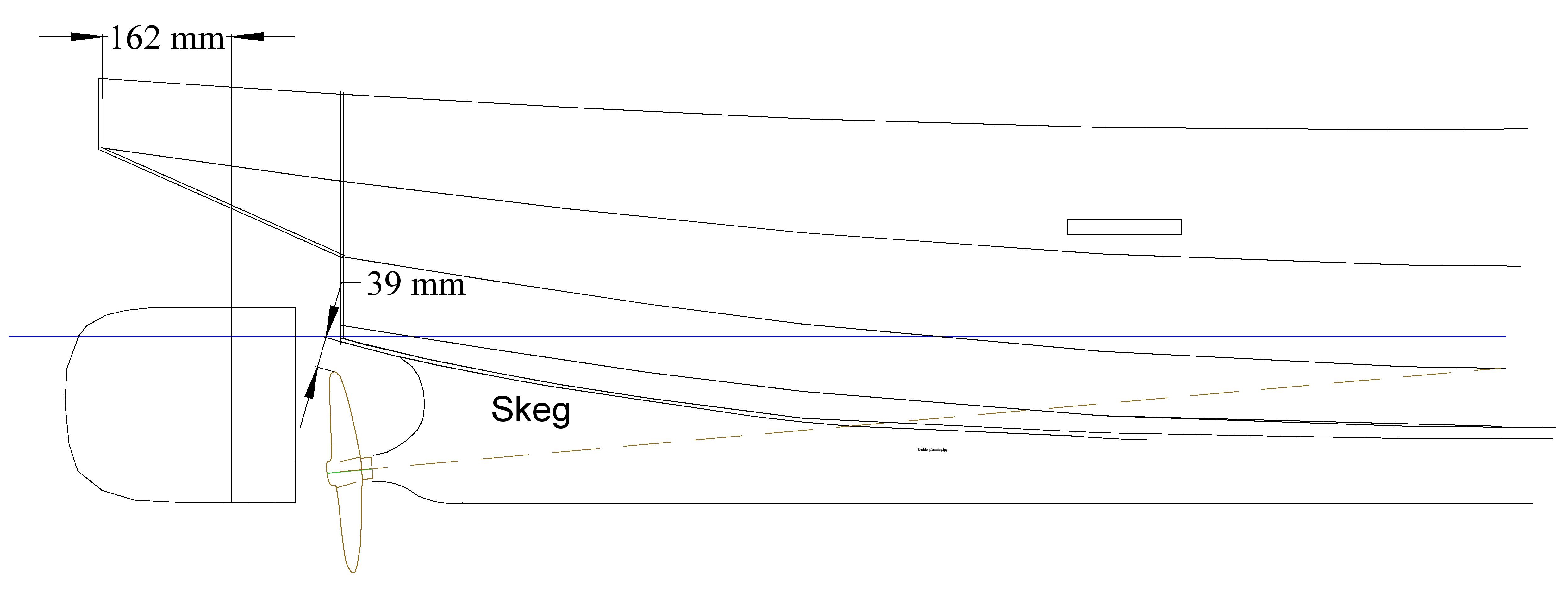
This change will still not meet all of Gerr's 'rules' as he advises that skegs should be cut back to allow a clear turbulence free frow of water to the propeller. The rule is that the cut back skeg should be no closer to the centre of a blade (i.e. 1/4 diameter) than 1/3 of the propeller diameter. One third of diameter is 85 mm for a 10" prop. For the lower half there is no problem as the skeg does not go that deep. However, the right angle could perhaps usefully be removed. Above the shaft the removal of a semi-circle would seem advisable if one is to follow the diagram in the Propeller Handbook. Thus the design moves on to the following layout:
The next step in planning would seem to be the specification and development of the propeller shaft and tube with associated bearings.