Mono-tube Boilers featured in Funnel
Funnel - Issue 15 p. 73. March 1978
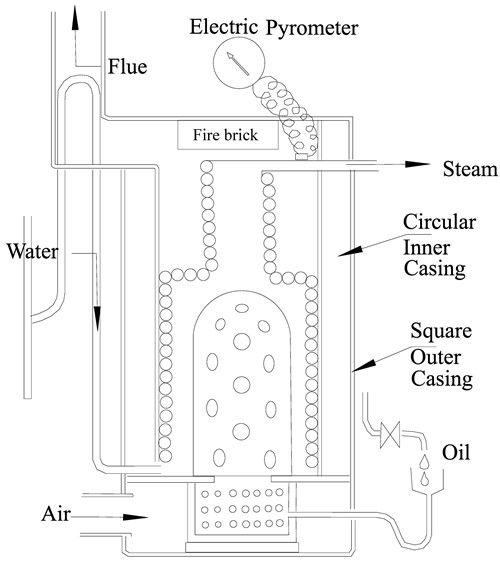
The lower part of the coil surrounds the fire and then takes a reduced diameter thus forcing the flue gasses to pass through it. It is likely that the coil at this point has a mixture of wet steam and water. Thus the top part of the coil provides a steam drier/superheater function.
Notice that the principal control readout is the electric pyrometer which shows the temperatue of the steam as it exits the boiler. Control of the fire is by varying the oil flow and the fan that provides the air. The system is over fed with water and there is a feedwater bypass valve to dynamically adjust the flow of water into the coil.
The coil comprises 50ft of 1/4" Red Spot steel steam pipe. The water pump is 7/16" bore by 1/4" stroke driven at engine speed which over feeds the system. The preferred operating temperature for steam is 260 C (500 F) which feeds a single cylinder uniflow engine.
Mr Wall reports the advantages of the mono-tube as being:
- It does not need cleaning
- It is realtively cheap and easy to make with limited workshop facilities.
- It is relatively light.
- No steam explosion hazard.
- It will easily stand any pressure ever used in marine plant.
- Steam is raised in a few minutes.
Funnel - Issue 45 p. 35. Autumn 1985 G B Young – A monotube boiler.
Mr Young's article is particularly interesting for those who like to experiment and monitor what is happening to the boiler in great detail. Careful examination of his schematic shows the numerous monitoring points and the built in safety features that are mostly pressure relief or fire shut down controls. The physical boiler is designed as "a propane gas fired monotube boiler [that] will generate 10lbs of steam per hour per square foot of heating surface at 70 psig and 340 degrees F (171C) (24 degrees F of superheat) which ... will run a Stuart 5A at 300 RPM and drive a 17ft Boat at 4 - 5 knots"
The boiler was four pancake coils of 8mm OD copper pipe (0.1mm wall) inside a 17" diameter galvanised steel casing (See picture below). The gas burner was a Barter Type LP7 with a maximum heat output of 85,000 BTUs at 20 psi gas pressure.

A particularly interesting feature of Mr Young's design is that the boiler casing comprised a series of layers. The lowest was devoted to the gas burner, while the next related to the coils, above that was the section containing the feedwater pre-heater and finally there was the cap with a stub for the funnel. It seems that the idea was to make the whole boiler easy to modify since it was intended as a test rig.
The system had two steam driven pumps plus a hand pump for start up and emergency. Water pressure was controlled at 75psi by a self acting control valve. However, it appears as if the water flow was manually controlled by altering the pump flow when the feed pressure gauge showed less than 75psi. The temperature of the steam was appaarently controlled by monitoring its output temperature and adjusting the gas burner manually. The system includes a water separator (K.O. Pot) but does not include further heating to dry or superheat the steam.
The built in safety features include the automatic feed water by pass valve which opens at 75psi, while a temperature sensor on the main steam outlet turns off the gas if the temperature of the steam exceeds 204 C (400F). These two controls work on 12v and are set up to activate if the power fails or cabling is damaged.
Mr young reports the following results: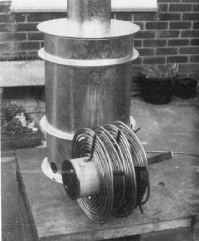
Ambient air temperature 60 F
Water inlet temperature 70F
water pressure, upstream of check valve 60psi
Water pressure downstream of check valve 60 psi
Rate of water flow 6.6 gals/hr
Equivalent steam 66 lbs/hr
Steam coil outlet pressure 50 psi
Engine RPM 240
Propane supply pressure 21 psi
Propane burner pressure 18 psi
Stack flue gas temp 260°F
Steam coil outlet temp 270°F
Funnel - Issue 48 p. 40. Summer 1986 Wally Mounster – Development of a modern steamboat – Part 1 – A monotube boiler.
This is an excellent article by an excellent engineer. Mr Mounster provides a useful list of issues that the would be mono-tube boiler builder should consider:
- It must be possible to bend the tube to the required shape without complex and expensive formers.
- Small bend radii must be avoided.
- All welds must be accessible for repair if they leak when tested.
- Spacing and retaining devices must be kept to a minimum.
- The layout of the tubes must encourage efficient heat transfer as much as possible by offering the hottest steam to the hottest part of the fire. By this I mean that the superheater should be close to the fire while the economiser section containing the cold water should be in the area where the flue gasses are about to leave the boiler casing.
Mr Mounster reports that he based his design on that of Scott & Newcombe's 1930s steam cars. He also used stainless steel having concerns about the level of corrosion from ordinary steel. The problem of chloride stress corrosion is also mentioned and the solution proposed was the use of high quality water and a condenser. The boiler was sized 'generously' having 250 ft (76.2M) of tube comprising three pieces; 5/8" in the superheater area, 1/2" in the main body reducing to 3/8" in the main evaporative area and then 5/16" in the economiser. The coil was developed over a simple wooden former.
This rather strange bottle shaped object makes much more sense when shown as a sectional drawing (below):

The casing was made of mild steel and so arranged to be easily removable in case of a requirement to maintain the coil. There is a layer of insulation and then an outer shell to protect passengers from the waste heat. The result is a very traditional looking steam launch boiler.
It is worth noting the baffle in the centre of the coil that forces the flue gasses to pass out though the coil before passing up the chimney. The fibrefax insulation in the firebox was subsequently covered by a stainless steel liner as the logs tended to damage it. There is a damper to allow control over the air flow into the boiler. Air flow is based on natural draught up the chimney.
The boiler is fired on wood and steam can be raised in about 4 minutes from cold. The boiler drives a 17ft average hull at hull speed using 10lbs (4.5kg) of wood per hour.
In his second article Mr Mounster explains the control system that he designed to manage the boiler.
Funnel - Issue 49 p. 33. Autumn 1986 Wally Mounster – Development of a modern steamboat – Part 2 - Boiler Control
Mr Mounster used a simple electronic control system which had three key control measurments; the temperature of the steam at the superheater outlet, the temperature of the liquid/steam at the half way point in the coil where the water ought to be all steam, and the temperature of the fire (using the flue gas temperature as a measureable surrogate). In practice it turned out that the second temperature was the key measurement for Mr Mounster while the third was useful for knowing when to re-fuel. The block diagram of his system is shown below:
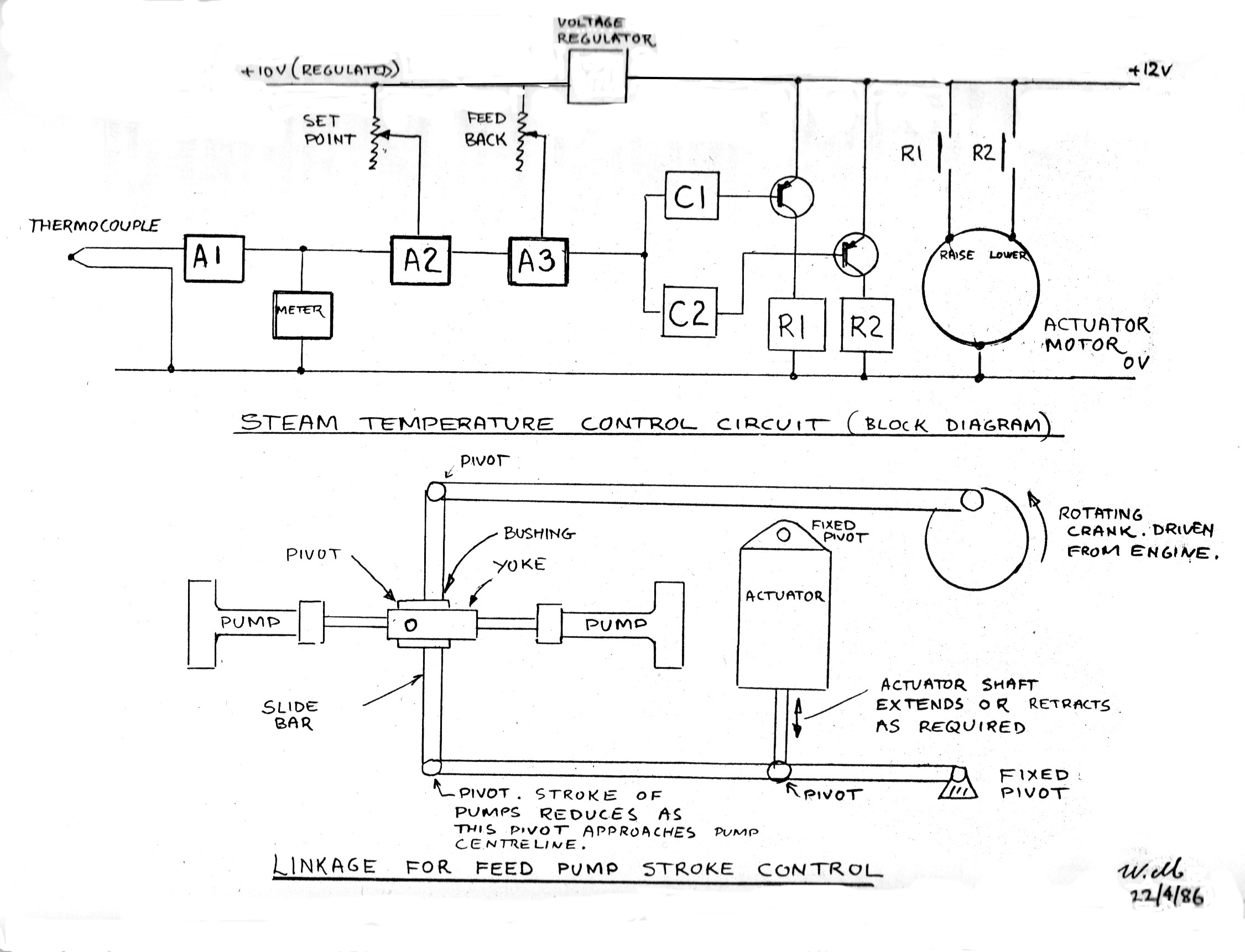 The voltage regulator outputs 10v and that current is adjusted by the potentiometer which is used to manually set the target temperature. The theromcouple measures the temperature of the steam at the coil mid-point in minivolts. This is amplified by A1 to give enough voltage to drive the display on the the meter. These two currents then go to A2 the second amplifier.
The actuator which adjustes the stroke of the feed pump also operates a potentiometer which provides a 'feedback' voltage. This is summed with the voltage from A2 and and amplified by A3. It then proceeds to C1 and C2.
If the temperature differs from the set point then there will be a difference in the output voltage. This is identified by the comparators C1 and C2 whose output is digital, a zero or 1. C2 has a reference voltage related to 'over temperature' and C1 is related to 'under temperature'. If (say) under temperature is identified then C1 will activate relay R1 which will activate the solenoid to raise the pivot arm, reducing the pump stroke and slowing the flow of feed water. The aim of the system is to make very small changes rather than large changes to the flow rate which assists in maintaining the stability of the system. The article also mentions that there is a second thermocouple, not shown in the diagram, that measures the temperature of the fire in the form of the flue gas temperature. It is not clear whether the temperature of the steam at the output of the superheater is measured by a thermocouple or a clamp on pipe thermometer.
Funnel - Issue 92 Spring 1997 p. 36 Jim White - Development of a small mono-tube steam generator
This is a very useful article for the potential mono-tube boiler builder seeking to power his/her steam launch. It reports how his previous mono-tube boiler in his 12ft dinghy, Daisy, had been very successful. That boiler had comprised 50ft of 1/4" tube fired by a Lune Vally type burner and driving a 2 1/4" X 3" single cylinder double acting engine at 400 rpm on 50 psi to a 4 blade 11 1/2" X 12" propeller On acquiring a larger 15ft boat, Skylark, he had decided to build a bigger mono-tube boiler, assuming that more steam would be required. The new design comprised 68ft of 3/8" tube. Sadly, the new boiler failed to work as well as the old one and the article reports upon his research to find out why. The key finding was that firstly, as we all know but often forget, a mono-tube boiler can only produce steam when and where there is water in the pipe. Thus extra length will not necessary increase evaporation, but will certainly increase the steam temperature. The second point, which again we all know but so often forget, is that steam is created by the water that is in contact with the hot metal of the pipe. However, the minute bubbles will form an insulating layer on the hot metal if they are not continuously brushed off by convection or water flow.
The article also reports research published in Model Engineer in 1931 by an author called E.T. It provides details of "tests carried out on three coils, each made from an eleven foot length, of either 3/16", 1/4", or 5/16" O.D. copper tubing all having the same wall thickness of 0.030", with water supplied by a variable output electric pump, and each coil heated in turn with the same standardized propane blowlamp, the steam escaping through a loaded outlet valve set to blow at 500 psi. In every test the 3/16" boiler gave the biggest output, and the 5/16" the least. The 3/16" coil evaporated 442gm/minute, but in a duplicate coil made of thicker 3/16" tubing, the evaporation increased to 495 gm/minute. The thickness is not specified but any increase must impede heat flow rather than help, even though by only a minute amount, so the consistent improvement found as the bore gets smaller and smaller must, it would seem, be due to the improved surface area to volume ratio. However, the resulting increase in velocity of the water-steam mixture, may well be even more important."
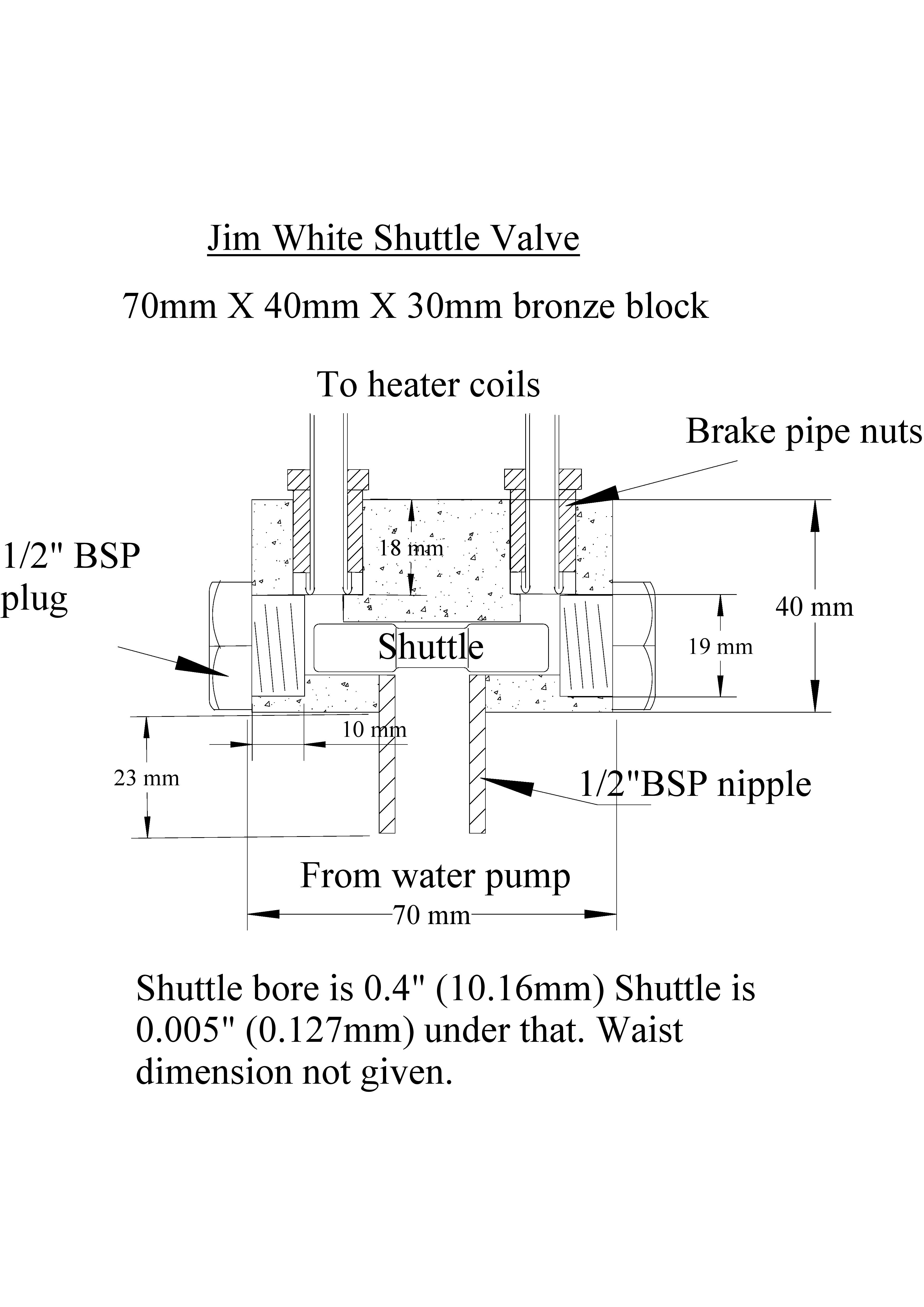
Clearly not a person to give up, Mr White then explores the idea of using a pair of coils to generate more steam. Apparently this had never worked successfully in the past because, with a single pumped supply, one or other of the tubes would get more water than the other. To overcome that problem he invented a shuttle valve that sits at the start of the inlet to the tubes and automatically adjust the water flow to each tube. The idea is simple as is shon in the diagram below. Also shown is the final schematic of his 'bigger' boiler which uses standard brake fittings for all joints, courtesy of his local garage.
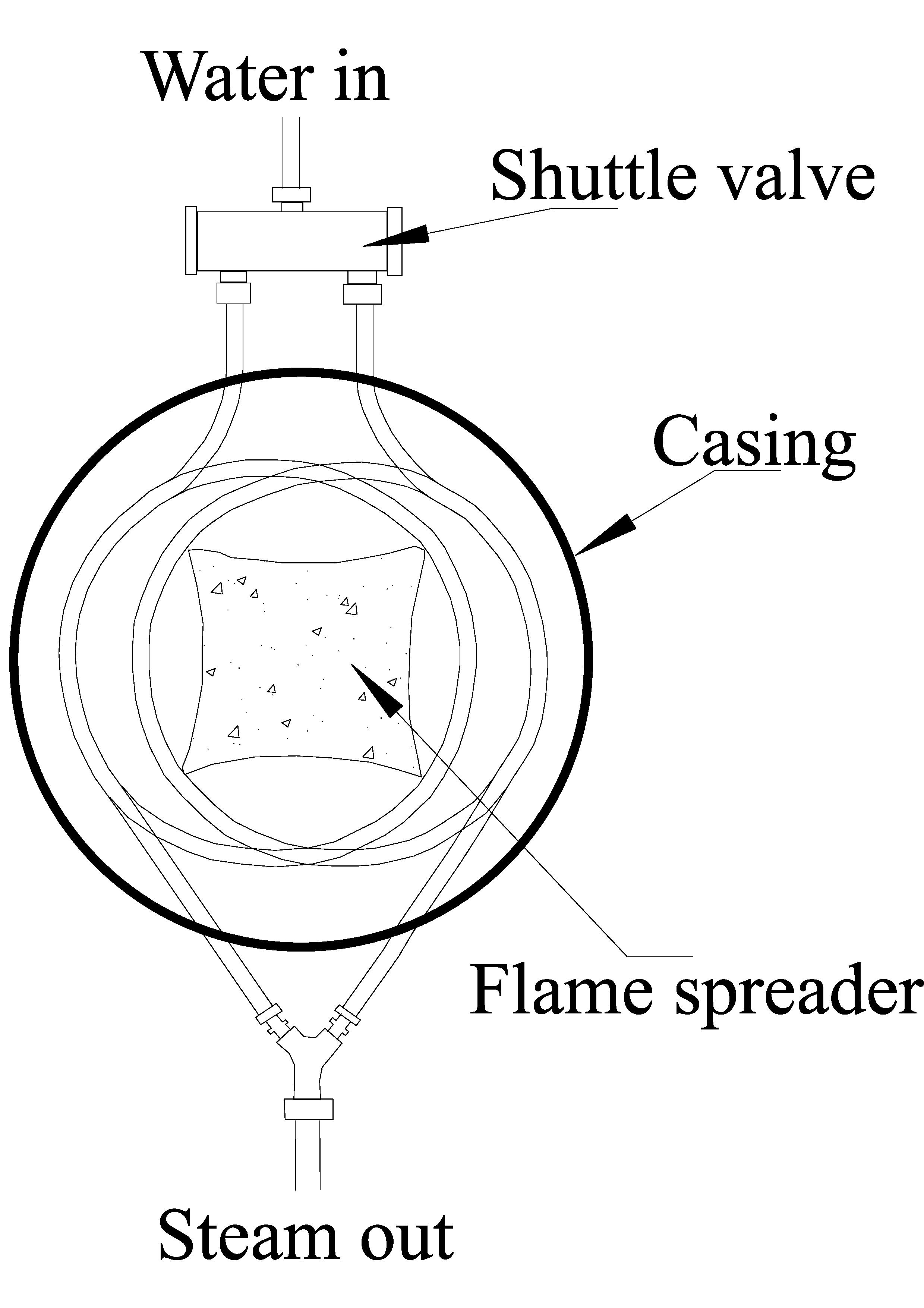
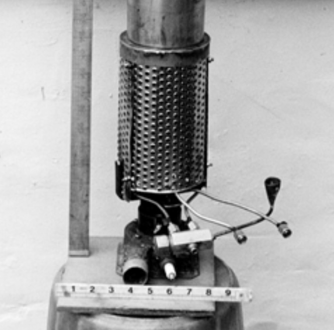
The photo shows the basic boiler which has been placed within an old washing machine drum. Note the spark plug at the bottom, presumably part of the burner mechanism and then above it the rectangular box of the shuttle valve.