Closed Loop operation of Mono-tube boilers
Although there are many variations of small steamboat plants currently used in the UK, probably the majority of boats have a single or simple compound engine with a skin condenser, similar to the types of plants that were used in the last commercial steamboats in Edwardian times.
In this cycle, the feed water circuit forms a closed loop of boiler - engine - condenser - air (condensate) pump (or just back pressure), back to the hotwell and so returned to the boiler via the feed pump. The pump(s) are driven by the engine. This is in contrast to the fresh water “puffing” boats which use exhaust steam to draw the fire, much as a railway locomotive does.
Since the water in a condensing boat runs in a closed loop, a level control spill valve on the hotwell ensures that the boiler water level control is automatic, make up water is only required to replace that lost from glands, blower and blowing off during manoeuvring.
In the case of monotube boilers, the two most common water feed arrangements are both currently open-loop. Model hydroplanes1 generally use measured fuel/water ratios with attendant high superheat, whilst full size boats use excess water feed with a steam separator, or a number of automatic arrangements.
The question arrises as to how a monotube boiler would behave if a constant volume of water was used. Fig 1 shows the water circuit;
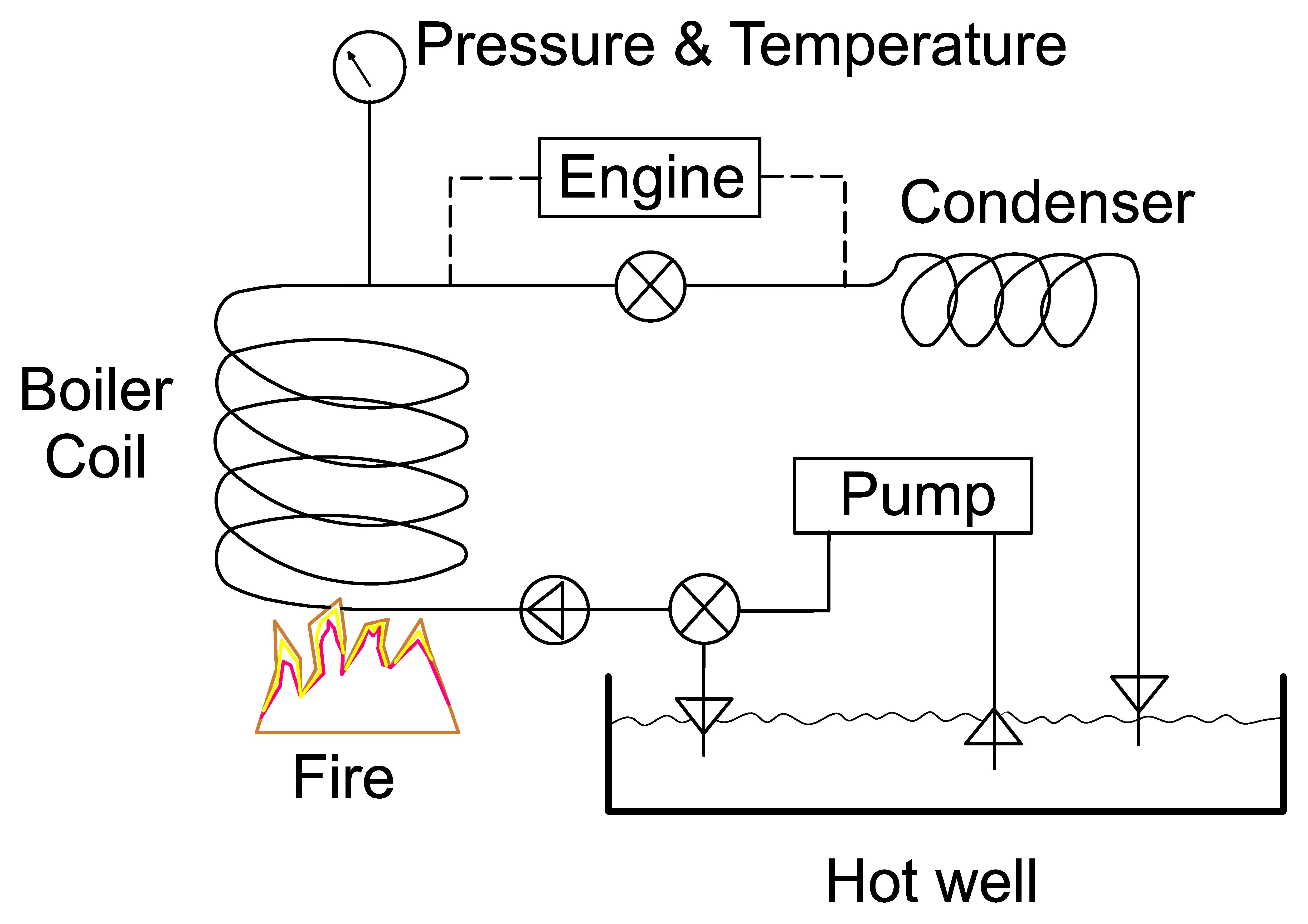 |
There is a slight oddity in the system pictured in Fig 1, in that the engine is bypassed by the throttle valve, rather than shutting off the boiler and blowing off steam. A variable pressure relief valve could be used for the bypass, so replacing the safety valve.This arrangement avoids loosing water whilst manoeuvring. Therefore to start the engine you close the valve.The system should suit most types of engine, and I see no reason not to add steam oil to the feed water, as extremes of superheat should not occur.
An engine feed pump with a float valve bypass into the hotwell, or an electric feed pump with a float switch could equally be used.
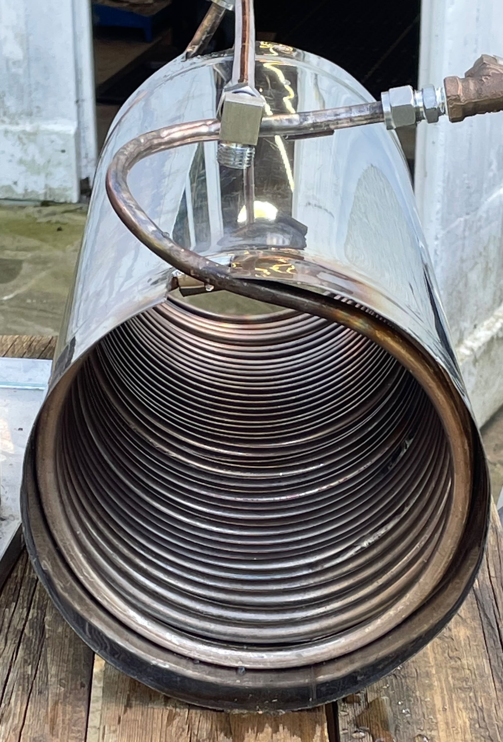
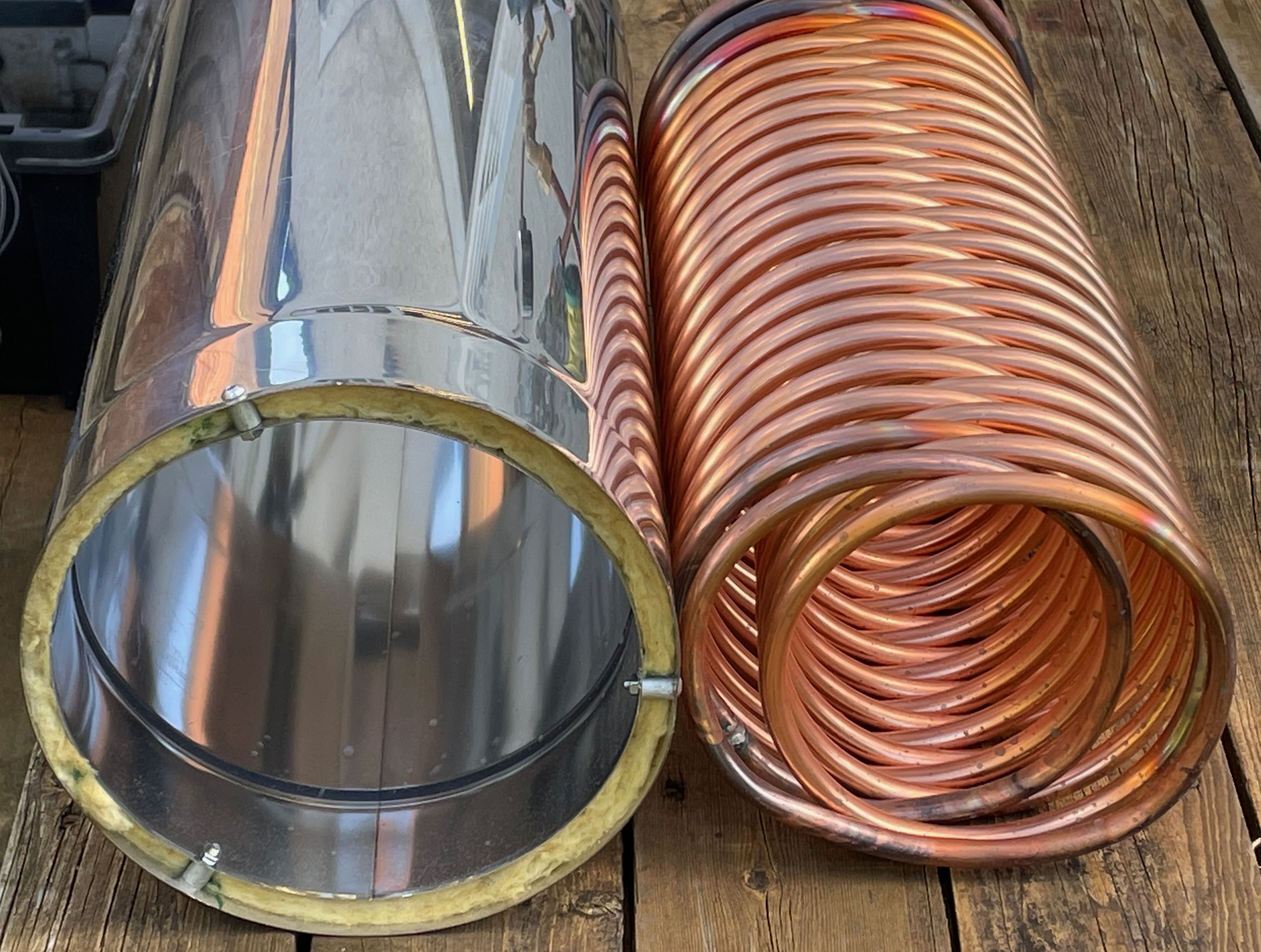
The figures below show the components of an experimental “rocket stove” boiler. Figure 2 is the grate and ash pan (8 inch cast iron drain cover), Fig 3 the lower plain kunifer coil firebox, and Fig 4 the upper “funnel” section. Fuel is dropped down the funnel.
 |
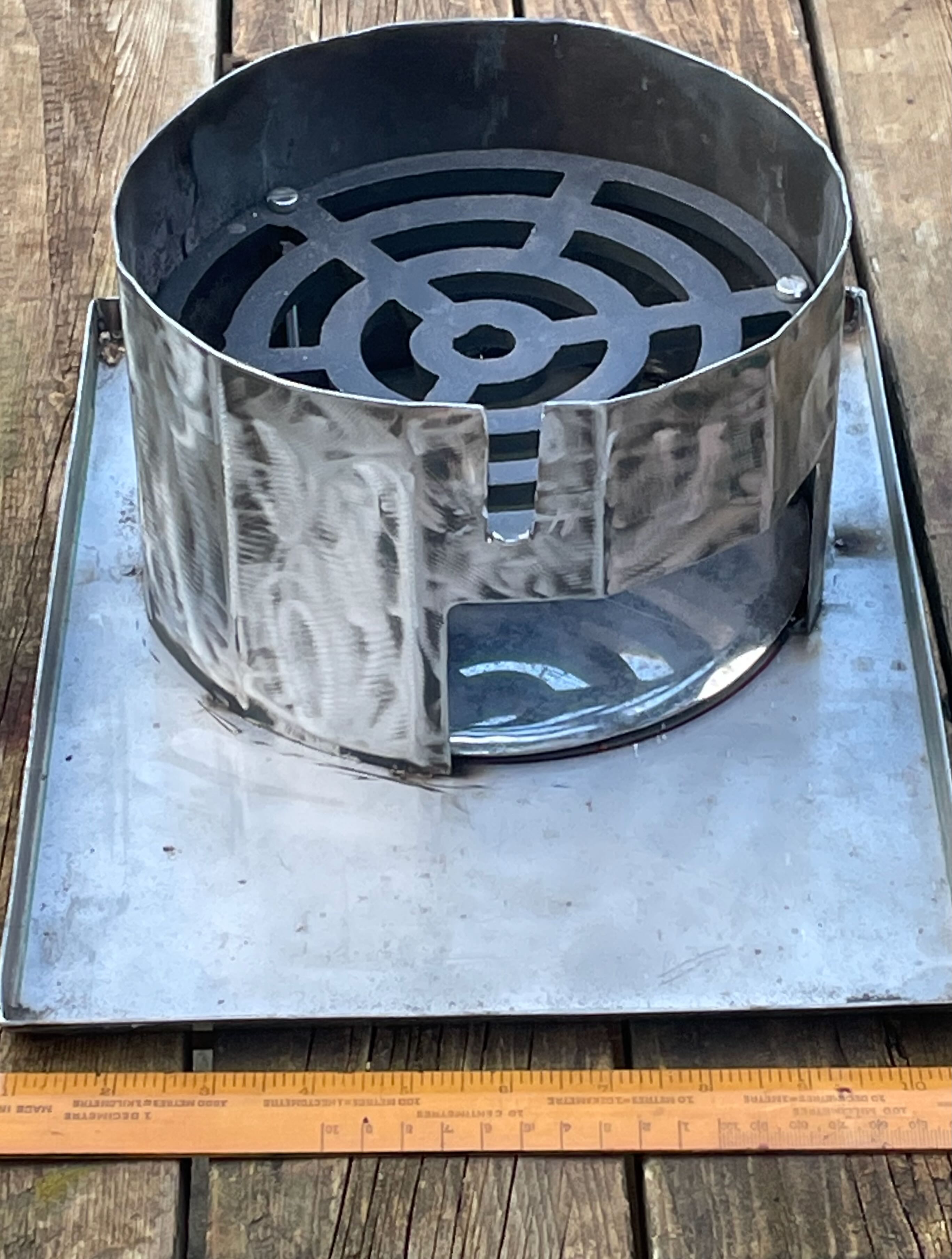 |
Fig 5 shows the whole arrangement, literally on the bench.
 |
Note that the hairpin tube supported on a chair back in Figure 5 is a hosepipe cooled condenser, delivering the condensate directly to the hotwell (no air pump).
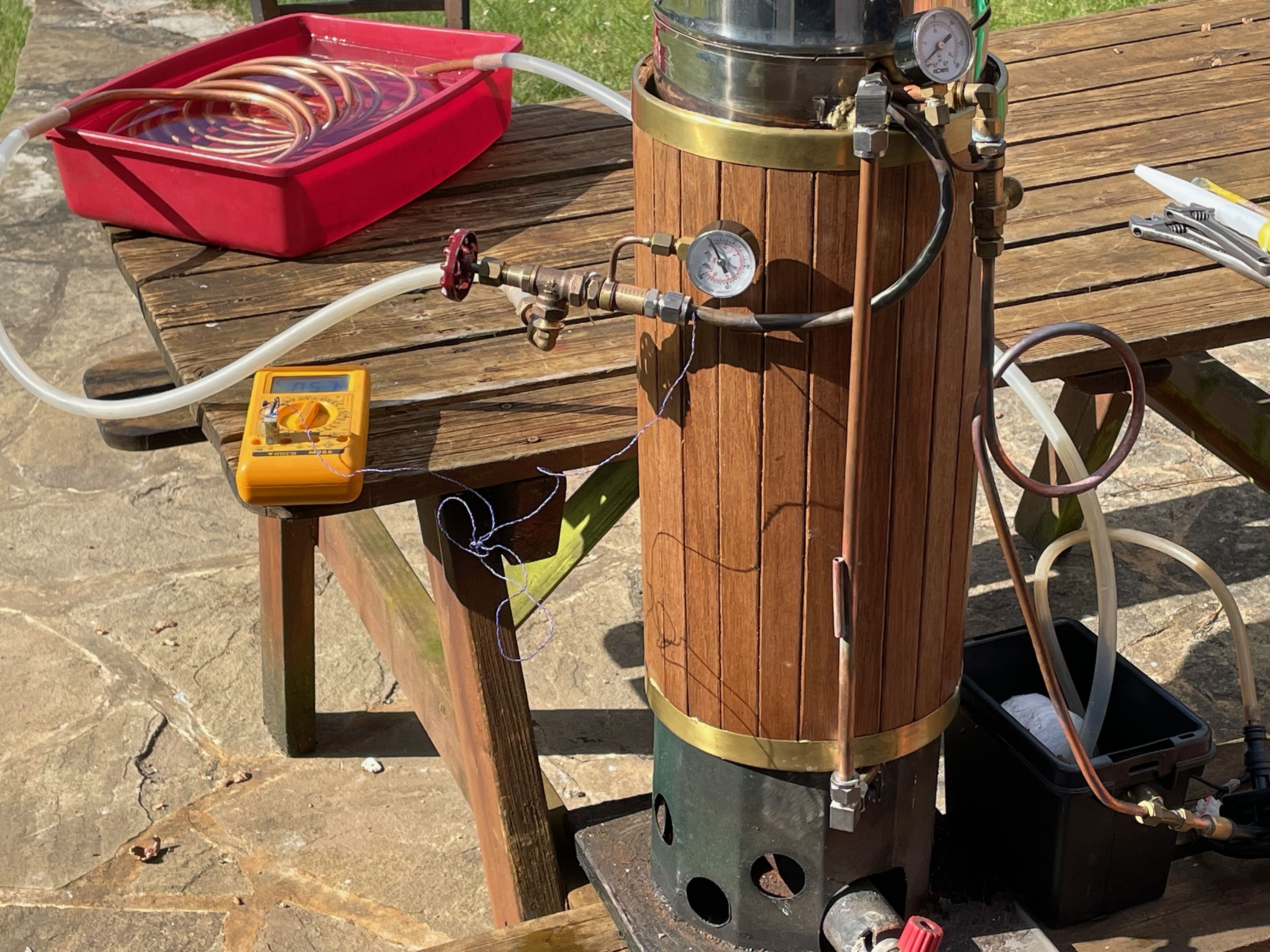 |
The bypass valve cracked open represents the engine in this arrangement, pressure being therefore variable.
By adjusting the total volume of water in the system, from roughly 20% to 80% of total boiler volume, on test it came as some surprise to find that the delivery of steam was stable in pressure and temperature under all conditions, although the wetness percentage could not be determined. The next step is to test on an engine, preferably with a dynamo load so overall efficiency can be estimated.
1 The late George Wall had a 20 foot boat called Nimrod, which used a stainless monotube run in just this way. He claimed that the poppet valve uniflow engine had an efficiency “sweet spot” when the head just glowed a dull red at dusk!