12th September 2026 - Playing with Water again
At this point in the Project the desk had a small pile of anti-static plastic bags containing various recent purchases. One was for the ADS1115 analogue to digital converter board that would take the signal from the pressure sensor and turn it into something that the Raspberry Pi could read. Another bag contained the DRV8825 driver board for controlling the stepper motor for the damper slider. A third bag was the channel relay device that would ultimately drive the opening and closing of the motorised valve.
Discussion with Deep Seek led to the provision of wiring guidance and Python test scripts for each of these devices. It seemed sensible to take the wiring guides and turn them into proper wiring diagrams as had been done with the displays. That helped to clarify how the items were wired and allowed some cross referencing of the instructions to instructions from elsewhere on the Internet. The pressure sensor diagram was the easiest to draw although the tiny text on the board itself was something of a challenge to read. Next work began on the stepper motor board and much tearing of hair began. Different publications seemed to use different labels for the pins leading to much confusion. Happily, there was a great number of articles about this particular board and eventually the most common names prevailed. It was during this period that it emerged that one might need to measure the current drawn by the stepper motor and set a potentiometer to keep it within a sensible range. The available multimeter has only a few functions and getting it to measure the current drawn by a stepper motor is probably beyond it's user's capabilities.
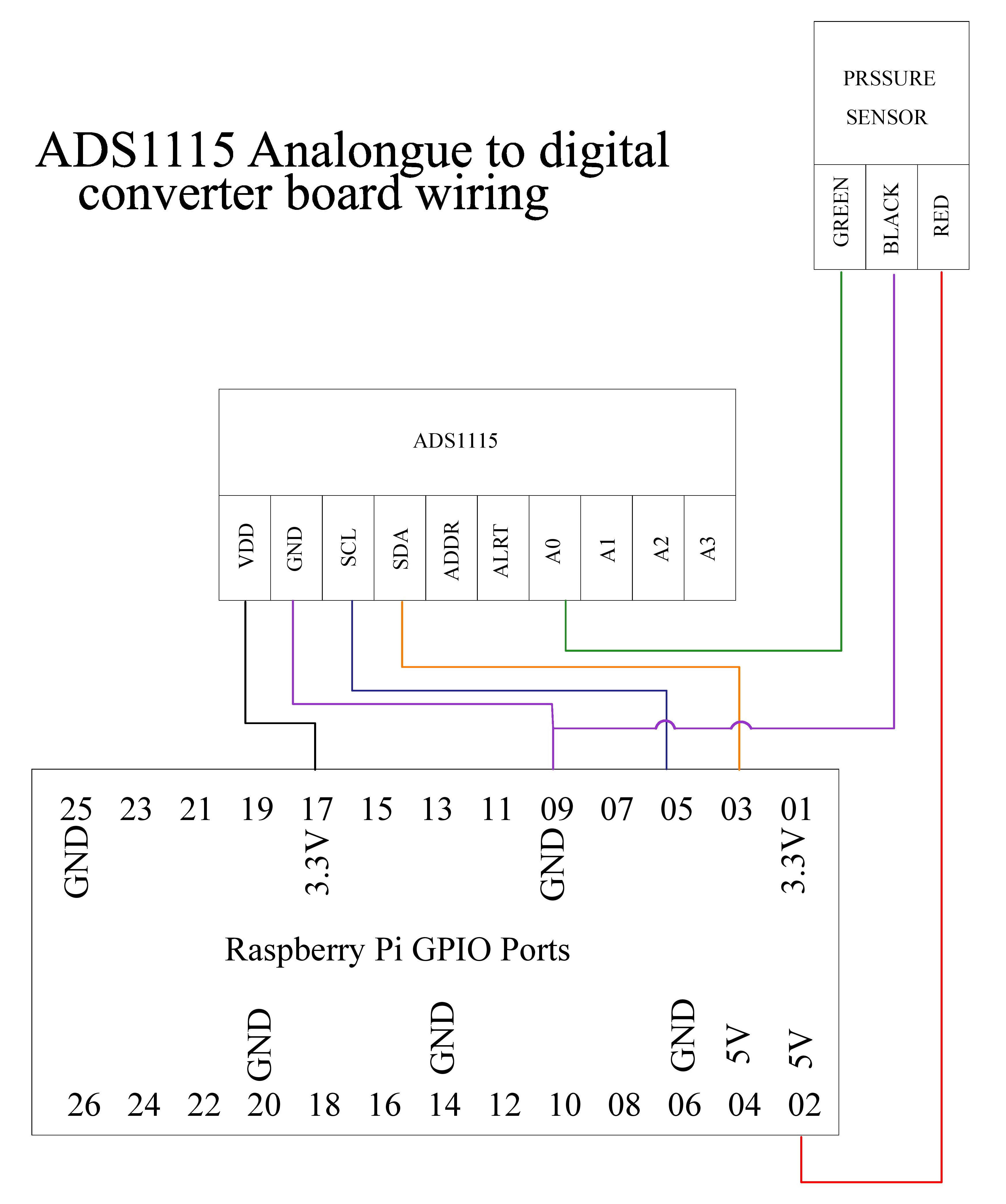 |
Since plentiful rainfall precluded work on the exterior domestic jobs list it was decided that the time had come to wire up the pressure sensor and see if it worked. Having the wiring diagram made the task relatively simple, but the amount of wiring already on the Pi led to much head scratching as well as difficulty in counting to the desired pin. By lunch time it looked as if there were enough wires in the right place to move to the test scripts.
Since the Pi runs on Linux one needs to be moderately familiar with its 'excentricities' which can make it very different from Windows at the command line level. The principal difference is that Linux supports the use of Virtual Machines which are instances of the operating system that runs independently from the 'main' system and have their own resources. For this project on the PI Deep Seek has instigated the setting up of a separate boiler build VM called 'boiler_env'. There is also a 'real' area where the VM files can be saved which we have also called 'boiler_env'. An important issue surrounded the need for the python scripts to be placed in the 'right storage place'. One needs to be aware of the the current physical directory versus the virtual environment which can have the same name without being linked.
Thus the screen prompt: (boiler_env) peter@raspberrypi:~ $ is full of 'clues'. The ~ at the end means one is in the real directory /home/peter — the home directory, (i.e top level) NOT the boiler_env folder. The (boiler_env) at the start means your virtual environment is activated, but that's a software context, not a location. As mentioned above , these two things share the same name 'boiler_env' but are completely different. The 'solution' is to start a session by getting the physical directory and the virtual environment in synch. The command cd ~/boiler_env gets one into the correct physical directory and then source ~/boiler_env/bin/activate gets one into the same virtual environment and finally that will be confirmed by the screen prompt which would be: (boiler_env) peter@raspberrypi:~/boiler_env $. Is this important for mono-tube boiler builders to know? Experience on this build shows that failing to understand it can waste much time by being in the wrong 'place' and wondering why nothing works.
The pressure sensor test script was run several times and the process of of working out why it would not give any results led to the finding of wiring mistakes, wires that had become unplugged and so on. A very tedious task but eventually everything on the software side worked. On the physical side the hand pump, with the pressure sensor mounted on its outlet port, was placed on the study floor on a tray. A small bucket of water was added to the collection and the flexible pipe connected to the pump's inlet. Much pumping seemed to remove water from bucket, but it was not obvious where it was going. In addition, the pump did not suddenly stop being easy to pump as was expected when it became full of water. Clearly the pressure must have been rising as the screen display showed ever increasing numbers.
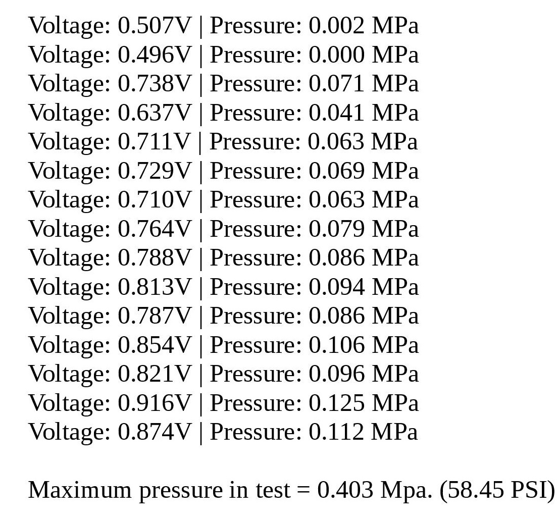 |
The performance of the pump was explained by Deep Seek as being down to the amount of air that was in it and the fact that air does not mind being compressed.
With that test successfully completed the next task was to sort out the stepper motor based system. Some earlier research had identified that the processor chip to run this task could be either a Texas Instruments DRV8825 or a A4988 chip by Allegro Systems. The comparisons considered that the Texas Instruments chip was probably better for this particular context which cleared the way for finding a supplier of the chip on a board with the other necessary electronics.
It seems that the boards in general use were designed by Pololu and have been widely copied by Chinese manufacturers. The result is that the market for the boards has a wide range of prices. The Pololu boards are offered at about £14 by various suppliers and are guaranteed to have high quality components. The boards at £5-6 will tend to have the real Texas Instruments chip but probably lesser quality ancilliary components. These are quite suitable for projects like this that will never get a great deal of hard use. The boards at £2-3 will be clones that have poor components and probably a cloned DRV8825 chip.
The middle priced boards were chosen with the buying decision directed by the offer of a board that clearly showed the TI logo on the chip and included a heat sink in the pack. With that product to hand, all that remained to do was to finish the wiring diagram and then set about connecting the board.