20th August - Water Control
As has been mentioned earlier a key component in the control system for the boiler is the mechanical valve that fine tunes the water flow to the heating coil with the skipper controlled PWM setting the pump output rate. Much time was spent chasing vendors of mechanical valves for information. The data collected suggested that there are plenty of valves which work on the principle that they are either open or closed. The partially opened mechanical valve appeared to be a rarity until one looked at sites whose valves cost more than one could ever imagine paying for a plumbing fitting.
Deep Seek suggested looking at Ali Express again as there were apparently many mechanical vales there at 12v or 24v which did not seem to appear for UK based searches. This was good advice and there were plenty of advertisments for low voltage mechanical pumps. Eventually, one vendor was spotted offering a 12-24v 6W three port valve. [https://www.aliexpress.com/item/1005011626409963.html?spm=a2g0o.order_list.order_list_main.5.2e871802l9qQMA] at £18 including shipping. That seemed like a safe buy even if the item was not very good.
Whilst on the AliExpress site various 'pop-ups' arrived, one of which was featuring a soldering clamp. It seemed a good idea to investigate and given that the item cost just over £1 also to buy one. The purchases arrived in due course and were examined. The brass casting for the three way valve was a nice heavy and well machined item. The motor was housed in an orange box but more importantly came with an instruction sheet in English rather than Chinglish. The ports are all 3/4" BSP so will need to be bushed down to 1/4" BSP to fit in with the rest of the plumbing.
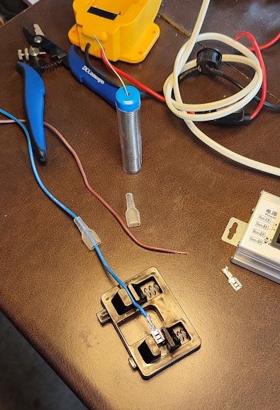
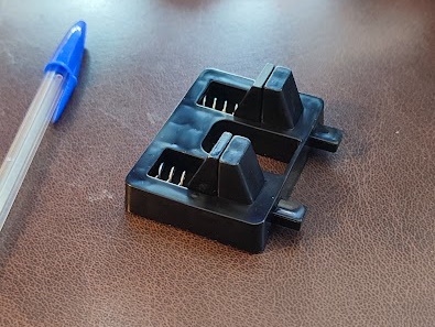
The wiring clamp was a neat little device but made of ordinary plastic. Thus it came off worst in a close encounter with a hot soldering iron. It was soon put to use as the next task on the agenda was to connect up the feed pump. That required a couple of leads with insulated spade clips.
 |
 |
Once these were soldered on, after some difficulty securing the clips in the device, the other ends were connected to the PWM box's leads'. Sharp eyed readers will have spotted that the spade clips are actually the crimp fitting type, but getting the wires secure with that method is not an available skill.
Next the whole collection was carried across to the Garage for temporary erection on the Terrace. The pump outlet was provided with a couple of temporary 'spouts' so as to give a visual indication of pump performance.
Once everything was connected up the battery was switched on and then the PWM with the setting turned to minimum. Nothing happened. The switches on the PWM were changed just in case the poles were the wrong way around. Again nothing. Everything was switched off and the battery was swapped for the spare and the whole routine repeated with the same result. It was then realised that the twist control on the PWM was set to 'Min' which actually might mean 'off'. The knob was carefully turned and the pump sleepily came to life.
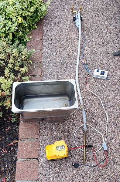 |
The expectation had been of two high fountains, but on reflection that was not sensible. The two spouts were hose mount connections whose diameter is 6.3mm thus allowing a good flow of water with not much constriction. One would have been much better. Anyway, the pump works and the controller also works well from a dribble to a good flow.
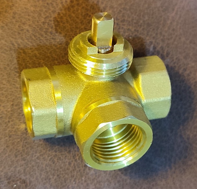 |
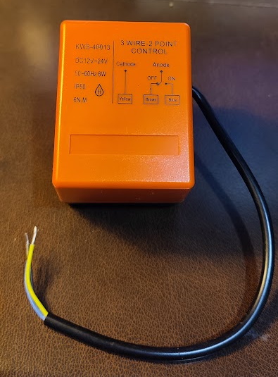
The whole set up was then dismantled and put away then thoughts turned to the next water related item. In this case it was the mechanical 3 way valve. This has a nicely cast body with neatly machined ports making it look like a good quality product. The motor body is a sturdy orange plastic 'box' which again seems well made and robust. It also has a basic wiring diagram on the top. There are three leads.
Whilst there was an urge to test the device there was also a small collection of problems to overcome. Firstly the ports are 1/2" BSP so three reducing rings are required to connect to the 1/4" BSP plumbing. Local plumbing merchants did not have such things so eBay was put to use. There was also a need to change the ports to coned rather than screwed so further adaptors were required. This time eBay was not able to help and AliExpress had to do the job.
 |
The other obstacle to testing was that it was going to require a power source, which was available from one of the batteries and a control mechanism. Getting the Pi to control the motor will probably require another Analogue-Digital converter, but advice on the best way to handle task has yet to be obtained from Deep Seek as the issue of the damper was providing a diversion. The damper control project will be recounted next and getting the diverter valve to work will follow.
Asking around various expert in the steam boating and model engineering arena yielded a range of solutions to the problem of setting up a mechanism to slide the damper under computer control. Linear actuators were suggested but their bodies were huge in the length required for the dampers' motion. They turned out to be quite expensive in the longer lengths. Another suggestion was a big cheap metal geared servo which sounded excellent until the degree of motion they could give was established. The damper needs at least 200mm which was way beyond the ones that were advertised. Another suggestion took inspiration from elderly radios and suggested the old-fashioned tuning system on radios with linear tuning display. The damper could be drawn one way or the other by a thin flexible wire or fine chain that runs round a pulley at each end and then to the nut on your lead screw via another pair of pulleys, one being adjustable or spring loaded. The idea seemed good, but not too easy to implement.
Finally, taking inspiration from the elderly lathe in the workshop whose whose saddle is moved by a small hand wheel at the right hand end and a long threaded bar it seemed sensible to investigate lead screws. The hand lever on the damper could have a brass bearing nut added and a piece of s/s threaded rod could be mounted with flat plates on the end faces of the boiler casing. One end, would have an electric motor attached to the threaded rod which, when rotated would move the slider.
Having found an eBay seller who appeared to be selling all the parts that might be needed a note was sent to ask if the concept was practicable and whether the vendor thought the suggested items would be sensible. The response was positive and so the parts were ordered. When they arrived it was clear that some of the assumptions I had made about parts from the photos were not correct. However it looked as if the system was going to work. A mock up was set up to see how it would all fit together which is shown below:
|
|
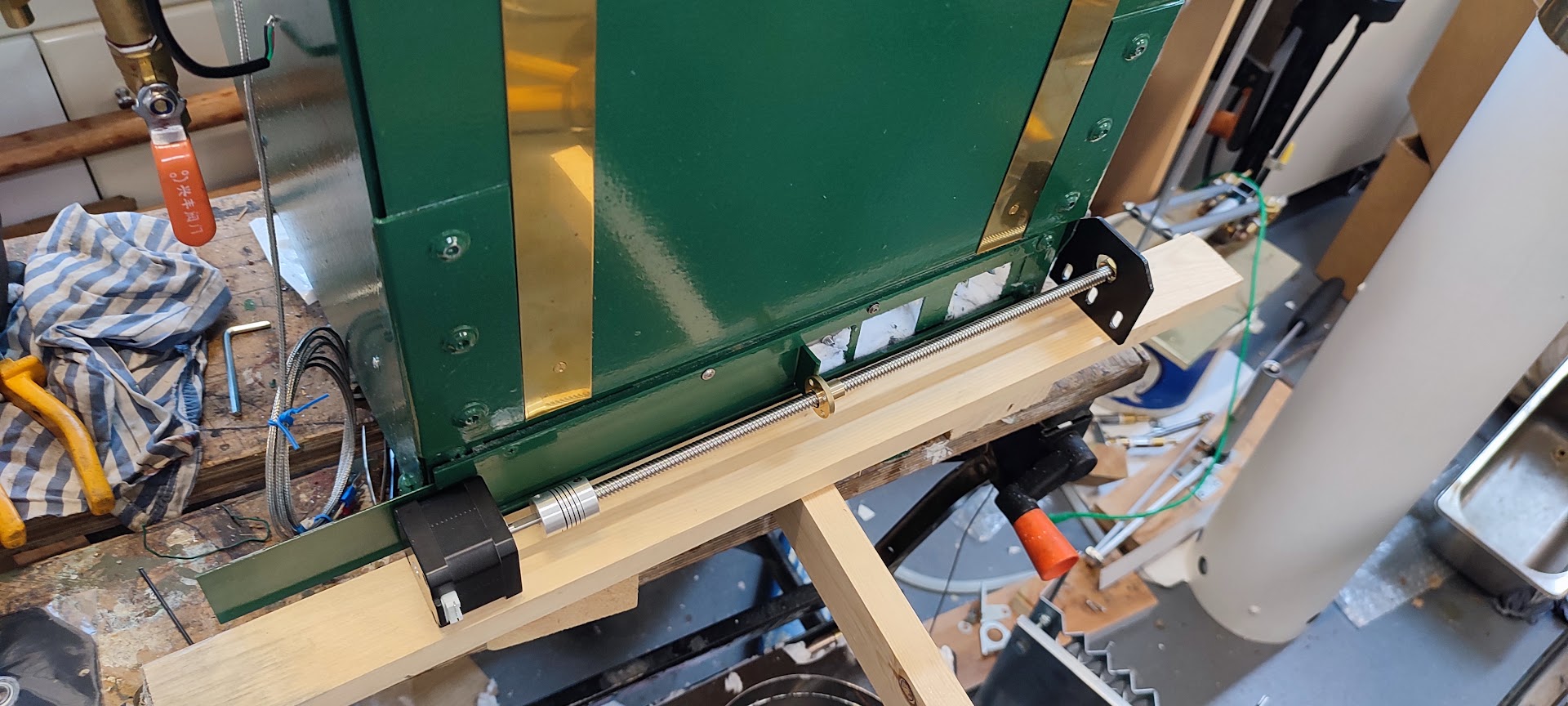
It was soon obvious that the motor mounting plate was not designed for the use I had in mind since it would have held the motor diagonally. Its holes were also slightly out of alignment with the holes in the end of the motor. In the end it was decided that a new motor mounting plate would be cut from some 5mm aluminium plate that was in the 'maybe useful in the future' heap. The plainer plate was used as a template and it was decided that each of the plates would be attached to aluminium angle plates that would be screwed to the body of the casing. The order would be motor, motor mounting plate, lead screw flexible joint, lead screw left end stop, mounting plate with bearing, lead screw nut, mounting plate with bearing, lead screw right end stop, mounting plate with bearing and finally hand crank if some suitable brass bar could be found.
Things appeared to be looking up but then the right side fire door was opened a bit. It was immediately clear that the side mounted hinges would effectively operate like guillotines for anything overhanging the ends of the casing. Needless to say, the design just worked out would overhang at each end. After much thinking it was obvious that the right hand fire door needed to be re-hung in a different way. The first question was to ask why the door was hung with side hinges. That was simply because John's boiler, the one on which this design was based, did it that way. Was there any reason why the door could not be hung differently? Nothing emerged so the problem was investigated. It emerged that the bottom of the door could probably be hinged to the boiler casing using a piano style hinge.
Some time was spent trying to find supplies of piano hinge in small lengths. This was not successful, but one supplier was willing to offer cut lengths. Thus a 300mm length of stainless hinge was purchased for the same price as a 1.8m length. Not a bargain, but hopefully a problem solved. While this was going on the efforts to sort out the stepper motor, mounting brackets, etc. had continued.
The home made mounting plate was carefully drilled on the milling machine as the correct spacing for the holes had been found in a drawing on the advert for the motor mounting plate that had been bought. Rather pleased that the holes had been drilled to an accuracy of two decimal places of a millimeter the motor was offered up for fixing. The M3 screws that were to hand were countersunk brass. They fitted but turned out to be too long. That was addressed with a degree of difficulty and then the plate was treated to the countersink. That pushed metal into the holes as well as removing it meaning that the holes had to be cleaned out with a drill. After all that the degree of accuracy in the soft aluminium has been compromised and the best 'quick' solution seemed to be to drill the holes out to M4. That worked but the final screwed up outcome looked rough.
Fitting the mounting plates to the boiler casing was going to require angle brackets as the lead screw equipment did not come with mounting brackets. A length of 'left over' aluminium angle was found and this provided three suitable lengths. These were marked up for their future fixing holes in the boiler casing. They were also marked up for fixing holes to the three plates. For the latter some stubby zink plated bolts had been found along with some matching nylock nuts. It was felt that the plates ought not to get hot enough to melt nylock nuts, but only experience will tell whether that was a sensible assumption.
With the mounting plates attached to the angle brackets it was possible to start a mock up assembly of all the pieces on a piece of plank. Persuading wood screws to locate perfectly is not easy and it was quickly realised that the three plates must be accurately located for the lead screw to align correctly with the holes in the plates. It may well be sensible to bore out the fixing holes in the angle brackets into slots to allow for flexibility in fitting.
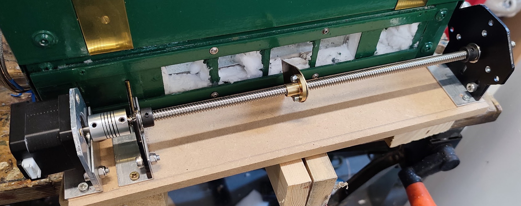 |
Some scrap brass was trimmed up and drilled to be attached to the lead screw nut. Drilling the hole to the right size for the neck on the screw was difficult as the strip of brass was insubstantial and needed to be held in a couple of pieces of wood. Drilling the holes to match the screw mounting holes was a similarly difficult task. It would, perhaps, have been more sensible to use a bit of the 5mm aluminium scrap. However, it was done in the end and attached to the nut. That finally mean the whole arrangement was completed in mock up form.
The next step in that context was to take the plank to the study and look up the wiring solution proposed by Deep Seek.