12th April 2026 - And now for some screens
Having mentioned the issue of the two thermocouples providing different temperatures while sitting on the desk to Deep Seek AI, a revised Python script was provided. This was copied into a new file and then run but it fell over at Line 3. It was calling "import board" so I queried whether 'board' was a variable that needed to be set up elsewhere. However it seems that it is a variant of Python which is peculiar to Adafruit, the manufacturer of the backpack boards that will drive the small screens. The solution was to install a library called Adafruit Blinka, which provides CircuitPython compatibility on Raspberry Pi (which runs standard Python). That process was not difficult but it took a fair amount of time.
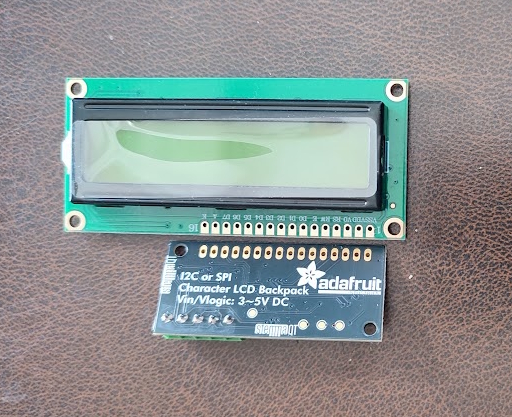
With Blinka installed it was then possible to test the operation of the screens. However, before that could be done it had been necessary to work out how to join the boards and the screens. The boards and the screens both have 16 hole 'spaces' for connectors to be installed. The screen's row of holes included markings for Pin 1 through to pin 16 in very small text. The Adafruit board had no such supporting markings. However it turned out that pin 1 is on the right hand end when one can see the Adafruit logo. It was also necessary to think about how the screens might be fitted into a project box and where the boards might go. Much thought led to the idea of a ribbon cable with 16 pin termination what could be soldered in place. However that did not seem to be an available product. The other possibility seemed to be a 16 pin header soldered in each device connected with socketed jumper leads. Finally a friend suggested that one could use a 16 pin header in one device and then in the other a 16 socket header. The outcome would be a solution where removing one of the devices would be simple.
That approach was taken and the first 16 pin header was set up for soldering using a desk top clamping workholder with magnifying glass. These are widely advertised, but seem to be less than good in use. Two problems emerged. Firstly, the header was flexible enough to bend in the middle so that it really needed three clamps, one at each end and one in the middle. The workholder only has two clamps.
 |
The second issue was that the pins to be soldered were not a tight fit in the holes so that the pins or sockets could be fixed other than at right angles to the board face. Finally, one also needs a very small soldering iron to avoid getting solder bridges between the holes. Clearly, this work requires much skill for the 'perfect' finish but that was rather lacking. Eventually all four sets of holes ended up with a header that appeared to be satisfactorily attached and without bridges. A run around with a continuity tester and close examination with the magnifying glass suggested that the work was good enough to be used.
With that done the next task was to sort out the wiring and how to cope with having two screens but only a limited number of suitable pins on the pi. The first task was to get a wiring diagram as something straight forward like that can make a great deal of difference when there seem to be too many wires all over the place.
The 'backpack' or breakout board has a simple screwed 5 terminal block which makes life a bit simpler. For this task it will be necessary to use the I2C communication technology which requires just two wires to be able to communicate with many devices. One wire is data and the other is the clock. The purpose of the clock signal is essentially to alert the recipient devices that a packet is coming and provide a guide to the data speed on the other line. However, the details of I2C are not that important as long as one follows the correct protocols to enable the parts using it to work.
For the Pi to Adafruit backpack the wiring diagram is thus:
|
Backpack Terminal |
Connect to Raspberry Pi Pin |
Pi Pin Function |
|---|---|---|
|
GND |
Pin 6 (or any GND pin) |
Ground |
|
3.5V (or VIN) |
Pin 1 (or Pin 17) |
3.3V Power |
|
DAT (SDA) |
Pin 3 |
GPIO 2 (I2C Data) |
|
CLK (SCL) |
Pin 5 |
GPIO 3 (I2C Clock) |
The useful thing about I2C is that it support many devices in either master or slave roles because each device will have a unique address. For the Adafruit backpack this address can be set by soldering over a pair of address jumper points. The default address for the backpacks is 0x20 so it was decided that one of them needed to be changed to 0x21. To do that jumper point A0 was soldered carefully on one device. The test for the backpack's address was to run sudo i2cdetect -y 1. That yielded 0x20 for both of them before the soldered connection but 0x20 and 0x21 afterwards.
To make life a little simpler it was decided to take a batch of jumper wires and set up both backpacks with the same colours for the same connections. Given that there is a need for two displays the wires were connected with Wago linear snap connectors and the 'standard' colour choices made getting the right pairs connected easy. Once both displays were wired up the i2cdetect command was run again and the display confirmed that two separate devices were identified.
At this stage there was a growing feeling of optimism and an expectation of the screen soon bursting into life. At that point both screen were brightly lit but there was no sign of anything related to characters. Under the tutelage of Deep Seek a number of tests were run all of which failed to bring the screens to life. Eventually, Deep Seek reported that the problem was probably the signal voltage to the display. The Pi's signal pin outputs 3.3v whereas the Adafruit Backpack really expects 5v since it is designed to work with the Ardino Uno microcomputer. Deep Seek suggested that a possible work around would be to add a Level Shifter to amplify the signal.
"A simple 4-channel bidirectional level shifter (e.g., TXS0108E or BSS138-based) converts the Pi's 3.3V I2C signals to 5V for the backpack.
Wiring:
|
Pi (3.3V side) |
Level Shifter | Backpack (5V side) |
|---|---|---|
|
3.3V (Pin 1) |
LV |
- |
|
5V (Pin 2) |
HV |
5V (Pin 2) |
|
GND (Pin 6) |
GND |
GND |
|
SDA (Pin 3) |
LV1 |
HV1 → SDA |
|
SCL (Pin 5) |
LV2 |
HV2 → SCL" |
Whilst this solution ought to work it was felt that the direction of travel was wrong. The solution meant adding yet another breakout unit and yet more wiring and thus the total level of 'clutter' was increasing. Fortunately, Deep Seek appreciated my complaint and suggested that the best solution was to abandon the Adafruit backpacks and the QAPASS 1602a screens. Instead I was advised to purchase a couple of screens that were known to be Pi compatible and, interestingly, did not require and external back pack to drive them. Using less hardware to achieve the same end was an improvement that warranted the extra cost.