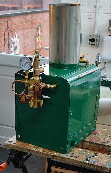
15 October (+) - More Plumbing
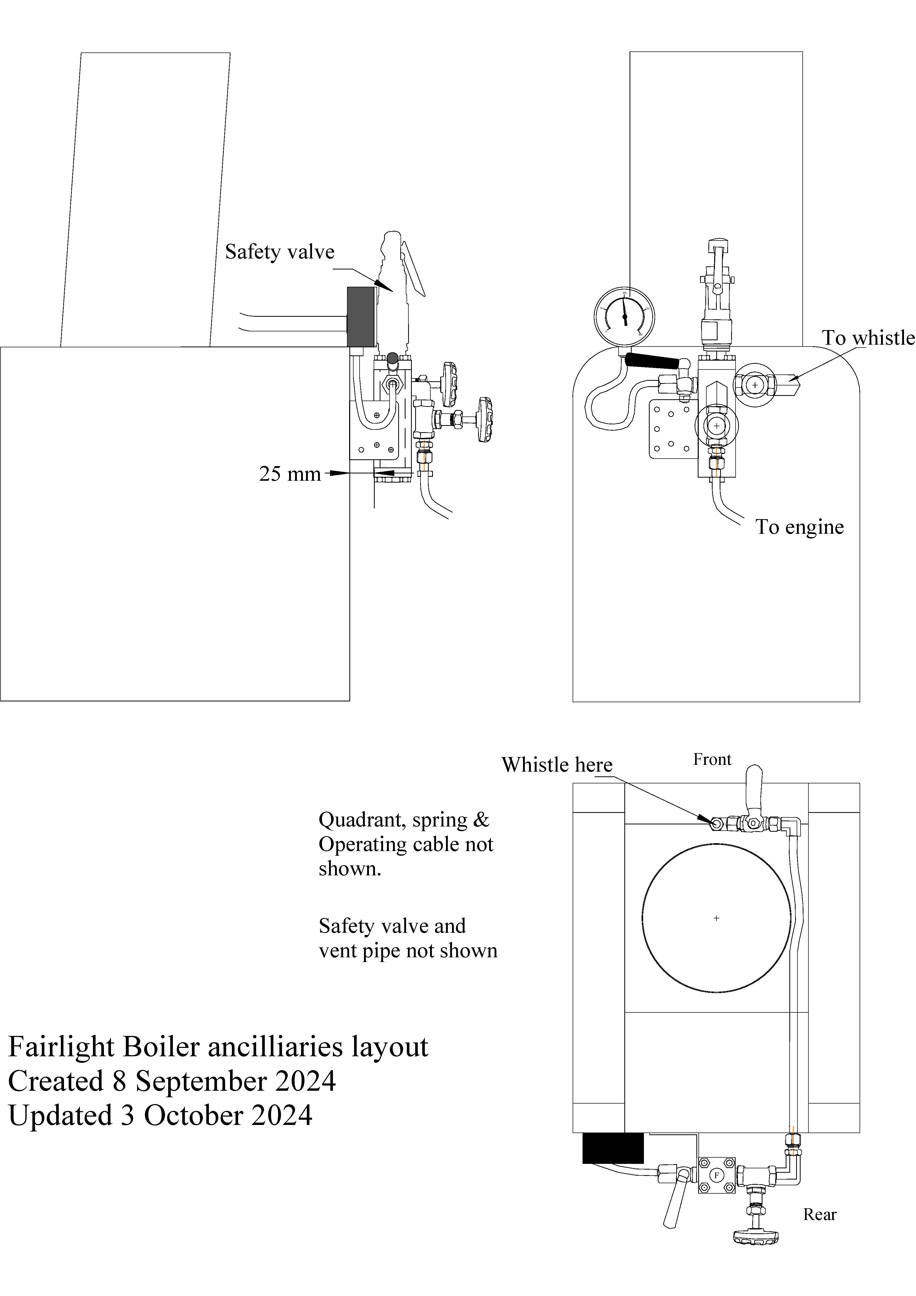
The approximate positions of the various ancilliaries was outlined in the section "Planning the Plumbing" of 10th November 2023. Actually implementing those ideas has turned out to need more careful drawing now that the various components are to hand and whose sizes are now known. The latest drawing has allowed the fixing of the whistle supply and the feedwater plumbing as well as locating the manifold itself. With those things fixed it should be possible to get closer to the final assembly of the casing. However, the drawing needed to be adjusted to take account of changes that seemed logical when working on the actual boiler casing. The planning drawing for the ancilliaries, although not fully completed, is shown below:
One of the skills of the good plumber is the ability to put bends in pipes that are in the right place when the pipe is fitted and to screw fitting up such that they end up in the correct orientation. As a very 'Coarse' plumber both those tasks have led to some head scratching.
Once many of the 1/4" BSP fittings were to hand it was found that despite what may have been advertised there seemed to be a mixture of tapered and parallel fittings. My preference was for parallel threads as I had assumed that one can pack the thread with PTFE tape to ensure that the item should end up tight in the right orientation. However, my assumption turned out to be wrong. I also tried using Stag jointing paste, although my tin was getting near to being time expired so the material was very thick. That was not a great deal better.
Thus I was faced with a problem of some fittings snugged up tight against the manifold but protruding a long way inside it. I also had a problem, especially with tapered fittings, of getting a 'tight' joint but having a long length of exposed thread remaining outside. To my eye that just did not seem 'right'.
Whilst some professional engineers will probably be be horrified, it seemed sensible to trim some fittings that have a long thread but are to be connected to a short threaded socket. Cutting these parts back was easy but has required some work with the 1/"4 BSP die if the part has a tapered thread. Sod's Law was very active and several of the shortened fittings snugged up to the body of the manifold satisfactorily but in the wrong orientation. The solution was suggested by a friend who advised buying a heap of flanged lock nuts. Thus troublesome elbows could be swapped around with the trimmed ends going into the globe valves both of which had very short sockets. The longer ends could then carry a lock nut and be screwed into place and fixed in the correct orientation.
In a similar vein some parts have been given a slightly longer thread by turning down a bit more of the body and extending the thread. This was done where a lock nut was needed and the thread available was not extensive. An example is the inverted tee that will form the plug onto which the whistle will be mounted. One arm of the tee goes through the casing with a locknut on the casing surface and then a cap nut on the under side which, when fully tightened, locks the tee firmly in place.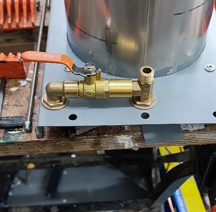
The fitting of the pressure gauge also caused some serious head scratching. My drawing assumed that the valve could screw into the manifold and thus be handy and horizontal. From that the pipe was intended to form some sort of U bend or loop and attach to the gauge. The latter was threaded 1/4" BSP but did not have the normal shape that a male connector would have. Querying this with the supplier I was informed that the gauge was normally screwed into the shut off valve socket. A swap was then done and it was quickly found that this position would not work as the valve handle would snag on the supply pipe. The answer came in a Toolstation Sale Promotion email. It was a 1/4" BSP brass connector tube which would screw onto the gauge while the other end could take a standard 1/4" tube connector.
Although things were looking up in the valve area, the remaining problem was to bend a piece of 1/4" pipe to make the connection. The first attempt with the small pipe bender was difficult and when finished was discovered to be the wrong 'hand'. A second attempt was started but stalled. Basically the bender is good for 90 degree bends but not 360 degree bends. In desperation a short piece of scaffolding tube was dug out and mounted in the vice. The half bent tube was then turned into a complete circle by hand around the pipe. Test fitting showed that the radius of the pipe was about right and the 'handing' was correct but it only needed to be 270 degrees not 360 degrees. A quick anneal then allowed the correct level of bend to installed. The final step was to consider how to secure the gauge so that it was not 'wobbling about'. Fortuitously, one of the fixing holes for the top panel of the casing was right behind the gauge so a simple flat bracket was easily prepared. 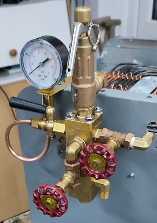 With that done the manifold looked to be pretty complete.
One slight advantage of this messing about with fittings is that I managed to discover that a pair of elbows from an eBay supplier were rather 'lighter' in their construction than I would have wished. In the particular case I had the elbow in the vice and was screwing into it another fitting with a reasobaly large wrench. On my final 'that should be tight enough' push the elbow collapsed. The mate to that part has been quarantined and replacements ordered elsewhere. It has been hard to find suppliers, whether UK based, eBay or Chinese, who actually provide a PN figure for their fittings in 1/4" BSP size. As a fall back I have relied upon the pictures provided and purchased if the item looks to have plenty of metal in it. I failed to do that with the collapsing elbow.
Another parts anomaly was in a set of parts from China in which the 1/4" BSP elbows have turned out to be 5/8"BSP. Those have gone into the 'possibly useful in the future' box as it is really not worth sending them back to China. I suppose that for these small low value orders suppliers perhaps take less care than might be the case with a bigger order.
With the position of the whistle fixed and the whistle valve, the position of the elbow back into the casing was derived. This was another fitting whose thread was 'lengthened' to allow the fitting of a flanged nut (See above). Inside the casing a second elbow was to screw onto the top elbow and lock it into position. Unfortunately the flange in the top panel of the casing meant that the elbow could not be turned. A variety of solutions were considered and rejected and the simplest was chosen. A short length was shaved off the top panel flange. With that sorted it was simply a case of tightening up the elbow and, whilst I was at it, fit the end cap on the whistle tee. The only trouble was that the two items failed to tighten down properly. The cause of the problem was the mounting plate for the funnel which was overlapping the 'swing' of the nuts but clear of the hole for the pipe. The only solution was yet another major strip down and then applying the base of the funnel stub to the guillotine. That enable the removal of a (wobbly) 5mm of metal and the nuts were then free to snug down level.
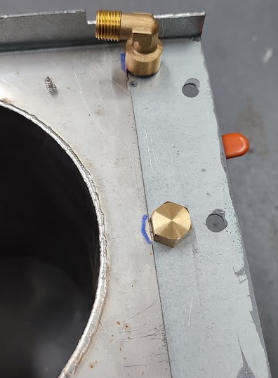 The final step in that piece of plumbing was to measure and bend the pipe from the whistle vale end to the isolating valve on the manifold. The two fittings were almost opposite to each other, but the aim was for the pipe to run on the insulation side of the insulation protection sheet. That meant an offset bend upwards at both ends. Being wary of getting it wrong I resorted to a wire template and used the pipe bender to make the offsets.
 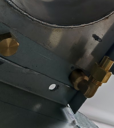 That was not easy as the bender was not keen on making two bends in opposite directions so close together. Coming to secure the pipe in its place it was realised that the hole in the end panel was too small to allow the nut to slide through. The only solution was to dismantle the casing (again) and drill the hole to a larger size. Drilling sheet metal with large diameter bits can be hazardous so I tend to clamp a bit of scrap wood across the hole to provide a medium into which the drill can continue rather than grabbing the metal and trying to rotate it. Happily, that worked out correctly so the last step was to 'final trim' the pipe, solder on the cones and then assemble. With that done the whistle plumbing was finished.
The next outstanding item was to fit the feed water pipe along with the pre-heat coil in the funnel stub. Theoretically that ought to have been easy as the casing was in pieces again and the insulation all removed. It was probably a bit premature to fit the insulation as early as it had been since many parts require access under or through it. However, the insulation protection sheets needed to be drilled before various bit of ancilliary stuff was fitted. Perhaps when everything is together it would be useful to prepare an 'ideal' assembly schedule to allow anybody following in our footsteps to avoid the assembly/dismantling process that has occurred.
The feed water heater coils were something of mystery as there seemed to be no advice anywhere that I could find about how much pipe to use. Thus I ended up making a coil of just over five circuits with a diameter to just fit inside the inner chimney. The coils were made by wrapping the pipe around a can of paint since that was about the required diameter. I did remember to start with the pipe that connects to the top heating coil and then do feedwater coils. The question then was how to lead the pipe back down into the casing. Even cutting the pipe would not have helped much so it was decided to run the pipe down the outside of the pre-heat coils. These were tightened up a bit first and then the whole device was forced into the inner funnel where it seemed reasonably secure despite having no fixings.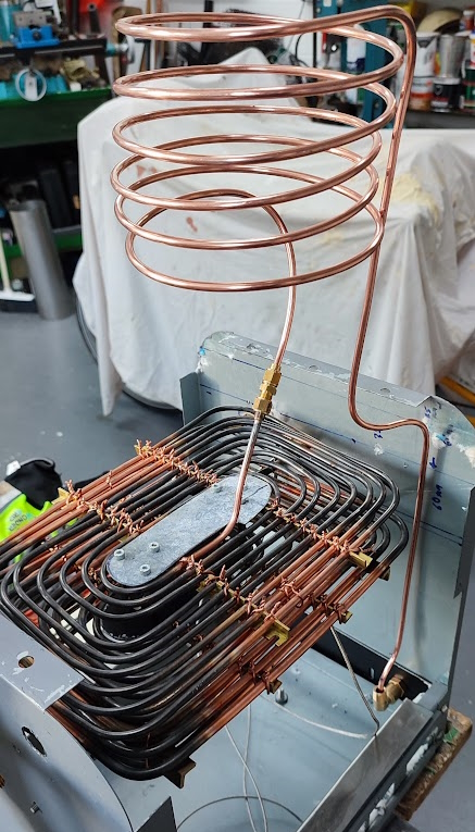
The link to the top heating coil was bent and marked as was the probable end of the pipe at the bottom of the casing. The coil was then pulled out and the top connection was cut. A model engineering fitting was found and the connection made without soldering the plug. A model engineering fitting was needed as that type of fitting was all I could find when the upper evaporation coil was being developed. The other end was not too far off but it was clear that it needed to be bent to bring it under the insulation protection panel. Reassembled without the funnel gave the following somewhat wacky picture (Left).
With those positions settled it was time to get the solder cones fitted to the ends of the pipe. Of course Sod's Law jumped into action and it was found that there were no more 3/16" cones. A quick dig into the Non-Fe bits box revealed that there were no handy sized bits of M10 bar available to use. The only solution was to move the milling machine (happily on castors) and get the packet of M10 brass rod bought a very long time ago. Once a small amount was cut off and everything put back the cones ware created and soldered into place, fortunately remembering to put the nuts on first.
Given that everything was in pieces it seemed sensible to get out the paint. The casing had been given coat of very smelly metal primer that refused to spread nicely and was reluctant to dry. In the end it was partially removed with white spirit. A new pot of more conventional metal primer was purchased and the casing was coated with that. The result was poor. The paint left significant brush marks and took a long time to dry. Even when dry its adhesion properties were poor. Smoothing it down before undercoating removed quite a lot of it which was disappointing.
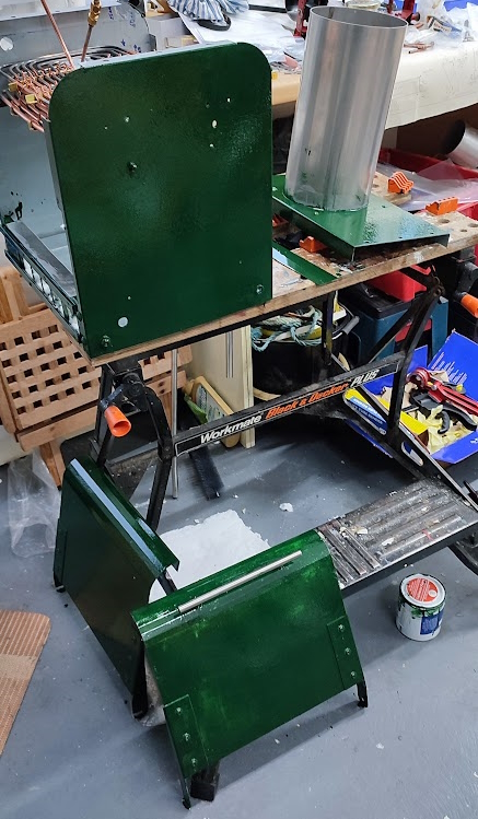 |
Happily, the Craft Master undercoat was a completely different material. It went on without leaving brush marks and was amenable to being applied with a roller. Its only downside was that if one was too generous with the roller, runs could emerge. Happily the undercoat was amenable to rubbing down so that most of the runs were removed or at least diminished.
The Crafts master top coat was also an excellent paint. It was applied with the roller from the start and care was taken not to be too generous. After application it looked as if the result would be satisfactory although not really to exhibition standard. Of course, at this stage it is not known just how this paint will stand up to the heat from the boiler. The majority of it should be separated by 25mm of insulation, but there are bound to be hot spots. This brand is widely used in the locomotive and traction engine community so I am hopeful that it will not all burn away.