19th August 2025 - A little bit of Hydro
19th August 2025 - A little bit of Hydro
With the hand pump now working well it seemed like a good time to begin the preparations for the hydro test. The draft plan for feedwater shown earlier seemed good enough, or at least no better ideas emerged, and thus the 'manifold' section to take the three inputs was created. One would be the hand pump, and the other two would be for the two electric pumps. A split union was acquired for where this manifold meets the plumbing for the feed water heater on the boiler. The idea of the splitable connecton was to support the fact that the boiler is meant to be removable from the canoe. It also is quite useful as it does allow the boiler to be removed while leaving the feed water pumping set out. What will be needed soon is a framework to support that plumbing plus the boiler to enable everything to be secured. That will require some reference to the boat plans, but that is jumping too far ahead since the boiler is not yet finished and ready for testing.
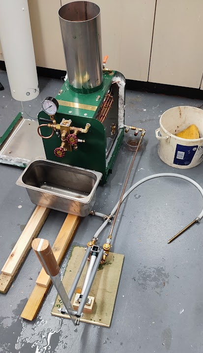
Whilst the manifold piece needed three inlets, only one of them was to be used for the hydro test; the one for the hand pump. That was quickly set up with a length of cunifer pipe and set at a length that put the pump close to the position of the engine. The other two inlets neeeded to be temporarily blanked off for the purposes of the test. A couple of brass discs were created to go inside a 1/4" BSP nut and it was assumed that they would pull down tight and be waterproof. Sadly, that turned out to be wrong. In the end the simplest solution was to acquire a couple of 1/4" BSP brass blanking caps which, with liberal application of Stag compound and PTFE tap gave a waterproof solution.
With all the relevant pipes connected, the hot well was filled and the hand pump set to work. It had been expected that with the bore of the monotube coil being so small, there would be sonsiderable effort required to pump water though it. That turned out not to be the case although the pressure required was probably alleviated by the fountain of leaks that appeared. Unfortunately, with the pump being so far from the boiler it was not possible to see exactly which bit of the various joints was leaking.
 |
Whist doing a mop of the now flooded garage, it was remembered that for traditional boilers the hydrro is done with the boiler fully exposed without any of its normal coverings. Clearly, that is what should have been done in the case of the monotube, if it was possible to arrange all the pipes in such a manner. Thereafter followed a somewhat depressing session of dismantling the casing yet again in order to remove the plumbing. The process was also quite difficult as the intention was to leave as much of the isulation protection panelling as possible in place. This was eventually achieved albeit with some worry about how easily it would all be put back together again.
The first pumpting session quickly identified that the short length of tube connecting the upper and lower coils was losing water. This was dismantled an examined. Both joints were coned joints so the leak was a surprise. However, it was spotted that one of the cones did not have a full bead of solder all the way around. It was clearly possible that I had overheated the pipe and solder had run out when doing the cone at the other end. The pipe was attached to a coned connector with the faulty cone exposed, mounted in the vice and then a fine cone of heat was applied from the blow lamp. That quickly enabled the cone to be removed and clearly showed that the joint was not soldered all the way around. Much effort was put into cleaning up that end of the pipe and the inside of the cone and then it was re-soldered. The bead of solder all the way around was encouraging and once cleaned up the pipe was replaced.
The next leak was also a surprise as that two was a coned joint. As a first check it was tightened up and more than expected movement achieved. As it sits in the funnel, it is clear that the 'final tighten' was not really tight due to the awkwardness of the access. Happily, the now tight joint will not need to be undone again for re-assembly.
The transition of the feed water piping from the front of the boiler to the feedwater heater section comprised a number of 'bits'. These were a coned connector, an elbow, a bulkhead unit and another elbow which connected to the split union. It was decided to re-work all the screwed joints from the coned connector and at the same time turn the bulkhead unit end for end. With that done and all tightened up it was unlikely that any of the items would need to be undone. The bulkhead unit would just need to be pushed through the hole in the casing and secured with a back nut.
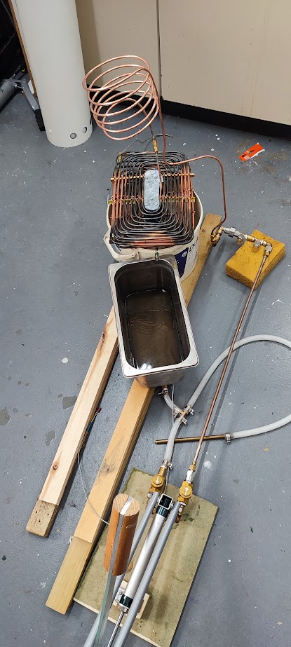 |
With that done, the 'outside bits' were added, the split connector joined up and the hot well re-filled. It was quickly found that the earlier leaks had been fixed and water happily poured out of the main coil where it would have joined the manifold had that item been connected. Strangely the water was initially very black as if it was flushing out soot. This little test at least showed that the joints were probably satisfactory and that attention should now move to the whistle piping.
Getting the whistle piping into place in the boiler top panel had been something of a challenge. However, it was eventually done and the insulation was added followed by the protection panel. The thought of taking it all apart again did not appeal so it had been put to one side. However, on finishing 'stage two' it was spotted that the main coil outlet was a cone and similarly the outlet of the whistle plumbing was a cone. Thus all that was needed was a coned connector to join the two and pump water across to the whistle side.
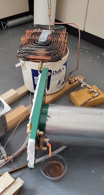 |
The connection was made and then the pump was activated again. There seemed to be some resistance, but no visible leaks and then it was realised that the whistle vale was probably closed. It was quickly opened and it delivered a slug of black water and then the flow turned to clear. The lack of leaks elsewhere was taken as being 'good enough' and thoughts moved to the final stage that would include the manifold.
The manifold was still in the state in which it was left for the initial tests of the hand pump. Thus the hose connector needed to be rmoved and replaced with a cone connector. Similarly the condensate drain needed to be set up with its tap and a length of pipe to take drainings to the hot well. Finally the main supply to the engine needed to be set up to receive the coned supply pipe. The pressure gauge would also need to be fitted but probably not until the final stage since such instrument are fairly robust but best treated with care.
The fittings for the manifold were assembled and fitted and then attention turned to the pressure gauge. It was added back to the manifold and then the manifold was attached to the coil. Next some pump strokes were made and it was noticed that the guage did not move, but happily there seemed to be no leaks. It was then spotted that the gauge isolating valve was set to off. That was quickly changed to on and the reward was a good spray of black water out of the pressure gauge loop. That came as a surprise as none of the coned joints had leaked so badly and that join was coned. The system was de-pressureised and the mess mopped up an then the manifold was removed and put in the vice where the troublesome joint could be examined.
One removing the joint it was found that the seat in the shut off valve was not coned. This was a surprise as I had some long time earlier decided to make it a coned connection on the grounds that the item had so much metal and a very small outlet to the pressure gauge. A 60 degree countersink with which to do the job had also been bought. Clearly, some distraction had prevented the job from being done. The countersink was retrieved and the task was started. Testing the cone with a spare solder cone the fit seemed poor. The reason was not immediately apparent, but then seeing the solder cone and the countersink together it was clear that the countersink was of too small a diameter. Checking the label on the box suggested that it should have been, but double checking with the caliper identified that the measurement on the box was for the length of the countersink's cone not its diameter. Needless to say the Internet was searched for another countersink with more than enough diameter. With the new tool, the cone was corectly cut and the test fit seemed excellent.
The gauge was re-connected to the manifold and that was re-connected to the coil. The pump was then activated and a good degree of pressure registered on the gauge (100psi) but at the same time there was a distinct feeling of being in the way of a watering can. Turning attemtion to the pump showed that the piston must have failed as water was being sprayed out of the air vent on the input stroke. With that problem it was obvious that the pump was in no condition to pressurise the monotube to twice its working pressure.