1st June 2025 - Non-Flexing Rolf Style Pump
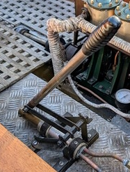
The solution to the flexing pump problem was found purely by chance in an advert for a launch on the SBA Small Ads section. The advert was for Egret 3 and the double stays for the pump handle looked promising.
 |
Rather than set to work in CAD and design this modification, a quick scan of the scrap pile was made and a large quantity of steel tube from a collapsed camping chair was spotted. A length was cut and drilled and the concept tested. It looked as if it would work. At that point the earlier Rolf pattern pump drawing was revisited and some editing work was started. It was obvious that one did not need to have double stays, but not having any more of the aluminium strip used for the handles, the camping chair frame pieces looked useful. It was assumed that the ideal movement for the handle would be with the 12 o'clock position at the half stroke stage. The other issue was the degree of gearing that would be sensible. Egret's pump looks to be very low geared as the distance between the piston connection and the pivot looks tiny compared to the length of the rest of the handle.
As the Rolf style pump's handle was already drilled it seemed sensible to use that drilling and then try to adjust the lengths of the two stays to get the desired movement. That process did not take too long and only a couple of shortening and re-drilling of holes was required. The process of getting the pump body secured required the use of one of the pump supplier’s custom brackets that I had bought but not used. That secured the piston end of the pump body while the former pivot brackets were ideal for the new layout. The two bracket styles put the pump body at different heights off the base which meant that a 6mm packing piece was required to get the pump body level.
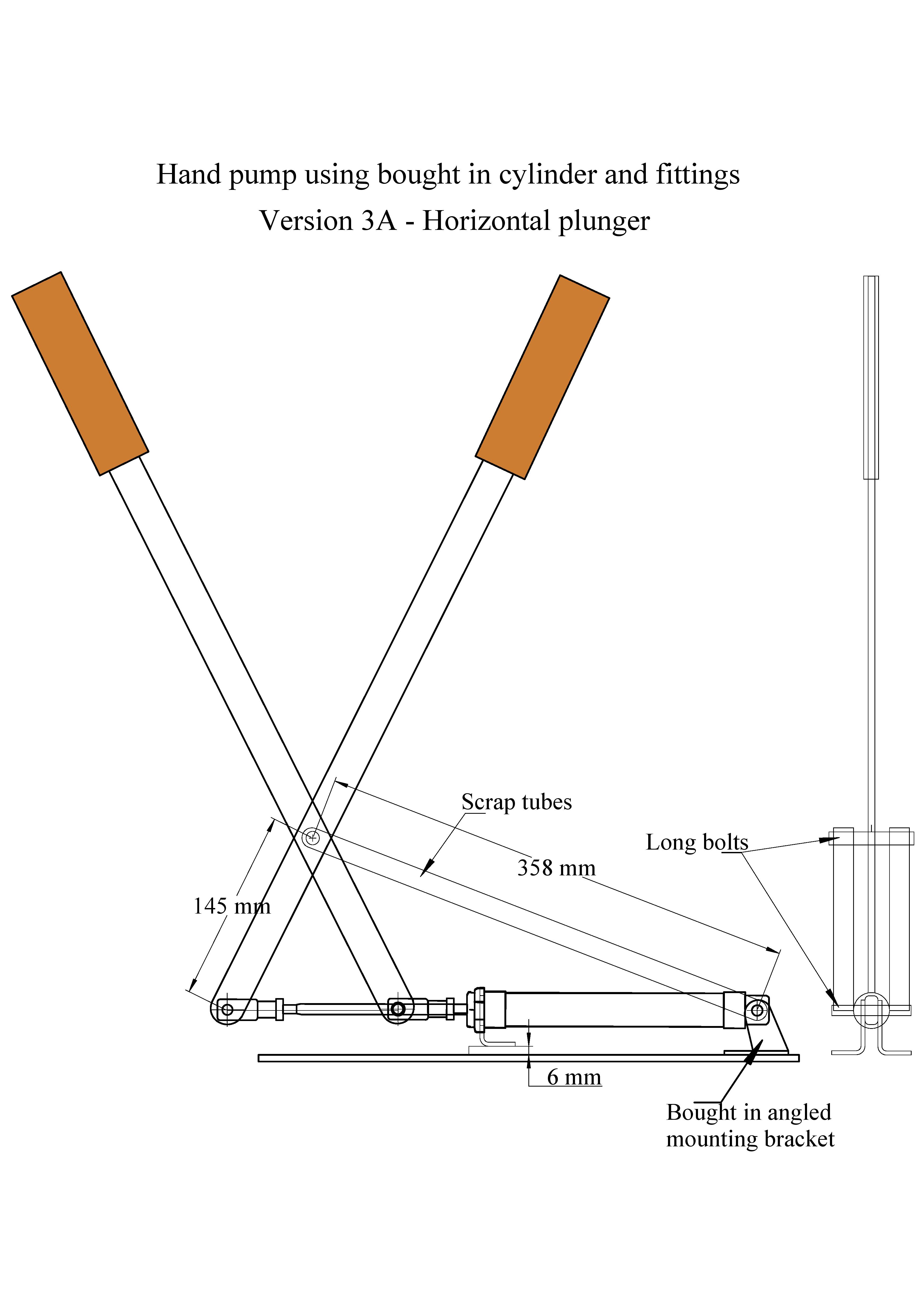 |
Since the concept clearly worked it was then a case of making spacers and getting washers so that the motion would be smooth and the new bars would be parallel. How close should the parallel bars be to the body of the pump? There was no obvious answer to that question, but they had to be rather wider than the body of the pump. Starting at the previous pivoting end two spacers were fabricated to ensure that the parallel bars cleared the pump body. At the other end slightly fatter spacers were required as the pump handle is only 5mm thick whereas the pivot end of the pump is about 10mm. There was some ‘twiddling’ to take account of the fact that the stay bars were round and so the bar end of the spacer need to be milled out to a nice fit. With all that in place the pump handle movement was nice and smooth.
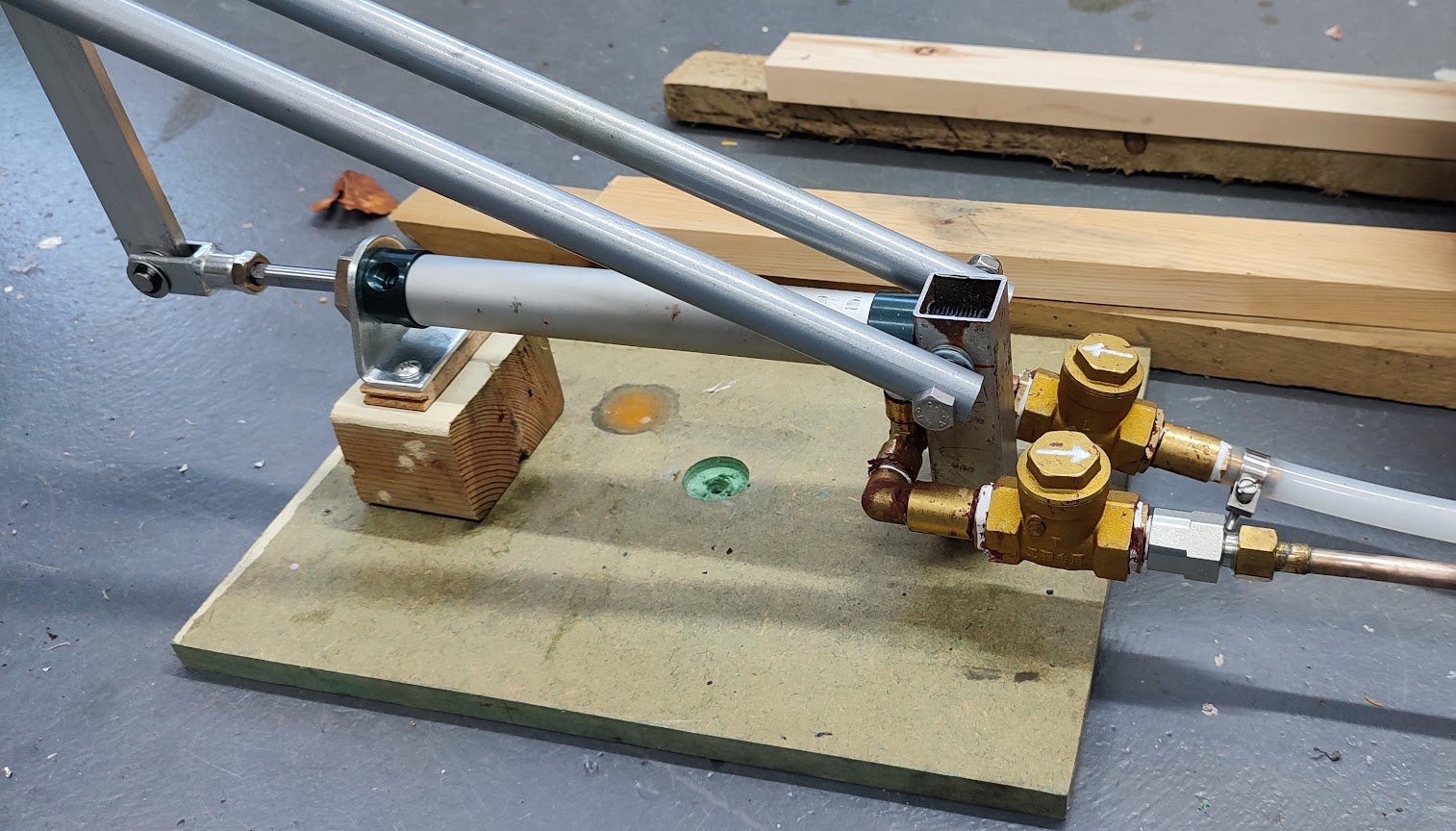
Unfortunately, real life does have a tendency to bite one’s ankle every so often. The next step was to plumb the pump ready to enable it to be used with the mono-tube boiler. That involved fitting the outlet/inlet connection plus elbows and the non return valves. That could either go on the top, at the sides or underneath. It seemed sensible at the time to put that plumbing underneath as it would probably help the pump to self prime. The pump, as drawn, was too low down to have room to fit that plumbing. The obvious solution was to raid the wood scrap box and raise the pump on a couple of blocks. That was quickly done, but it was discovered that a block big enough to take the front bracket was still in the way of the plumbing. Various bits of ‘cutting back’ ruined the block but did not solve the problem.
Several days later the idea appeared of mounting the ‘plumbing end’ of the pump on a metal pillar which could be cut with a slot to take the 10mm ‘tenon’ on the end of the pump. That could be kept in place with the through bolt on which the additional tubes pivot. No solid square section bar of suitable size was present in the scrap box but there was a short length of square section steel tube. This was of adequate length and it was decided to mill out a hole rather than to cut a slot, probably on the grounds that once mounted in the mill there was little further effort required. With great care the position of the cross bolt was measured and then drilled and happily the ‘post’ became secure. The plumbing was soon added and the various components for the hydro test were laid out and connected.
 |