23rd May 2026 - The Multiplexer
23rd May 2026 - The Multiplexer
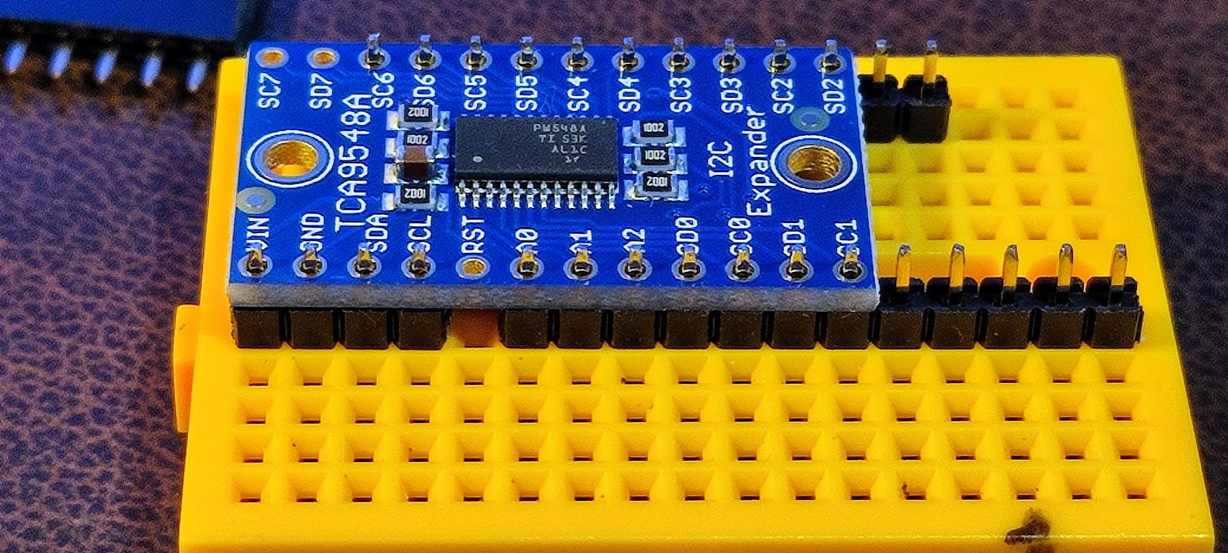
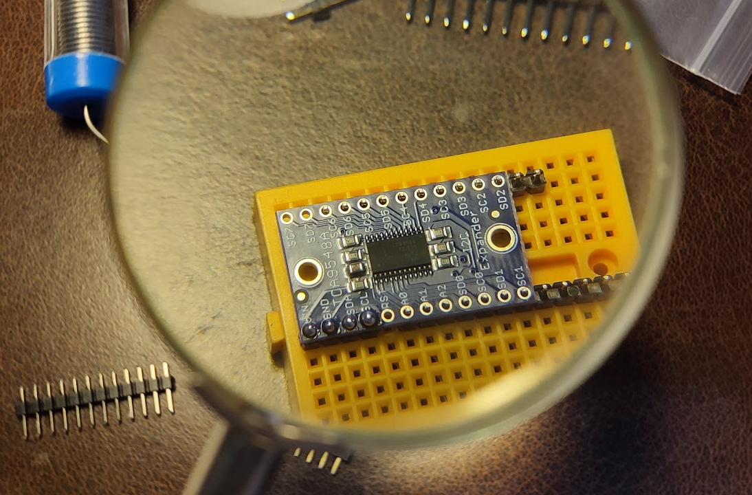
The multiplexer, like the first screens and backpacks comes with a row of holes along each of its long edges. Happily they are all marked in very small print so that there ought to be no confusion. The only difficulty is that they need header pins soldering into them. Given this particular application of the board there is only a need to solder in four pins which are all in close proximity so a four pin header is all that is needed. Deep Seek advised using a a breadboard as a 'clamp' for the pins. The four pins were cut off and then a couple of the remaining headers were lined up so that they supported the rest of the board for soldering. To save counting a gap of a couple of pins was left between the quartet and the support headers. This was certainly an excellent idea as everything seemed to be perfectly aligned and solid. The soldering was quite quickly done and put aside to cool before the assembly was dismantled.
 |
 |
The next day, or there abouts, it seemed sensible to query Deep Seek about the wiring of each of the boards into the multiplexer. The answers seemed logical but how to wire the board seemed to be a serious problem. Eventually, it dawned that each board would need to use the VIN pin for a 3.3v supply and also the GND pin to complete the circuit. Each board would also need a Clock Pin and Data Pin. That meant at least four more pins would need to be soldered into the board. There was, as might be imagined, some disgruntlement that this had not been mention or spotted when the first set of four pins was attached.
It was decided that the best solution would be to take the remaining header strips and set them up so that every hole ended up with a pin. Using the breadboard approach that task turned out to be easy enough and was soon done. However, the question of which wire would go to which pin needed to be answered. It was clear that the two boards would need their own Clock and Data pins meaning that four pins would be used, but which ones? The Power and Ground lines from the Pi would need to be added but since the Multiplexer only had one pin for each there was going to need for some sharing and Wago clips.
Ultimately, the solution came in the form of a CAD drawn wiring diagram that attempted to clarify Deep Seek's text only instructions.
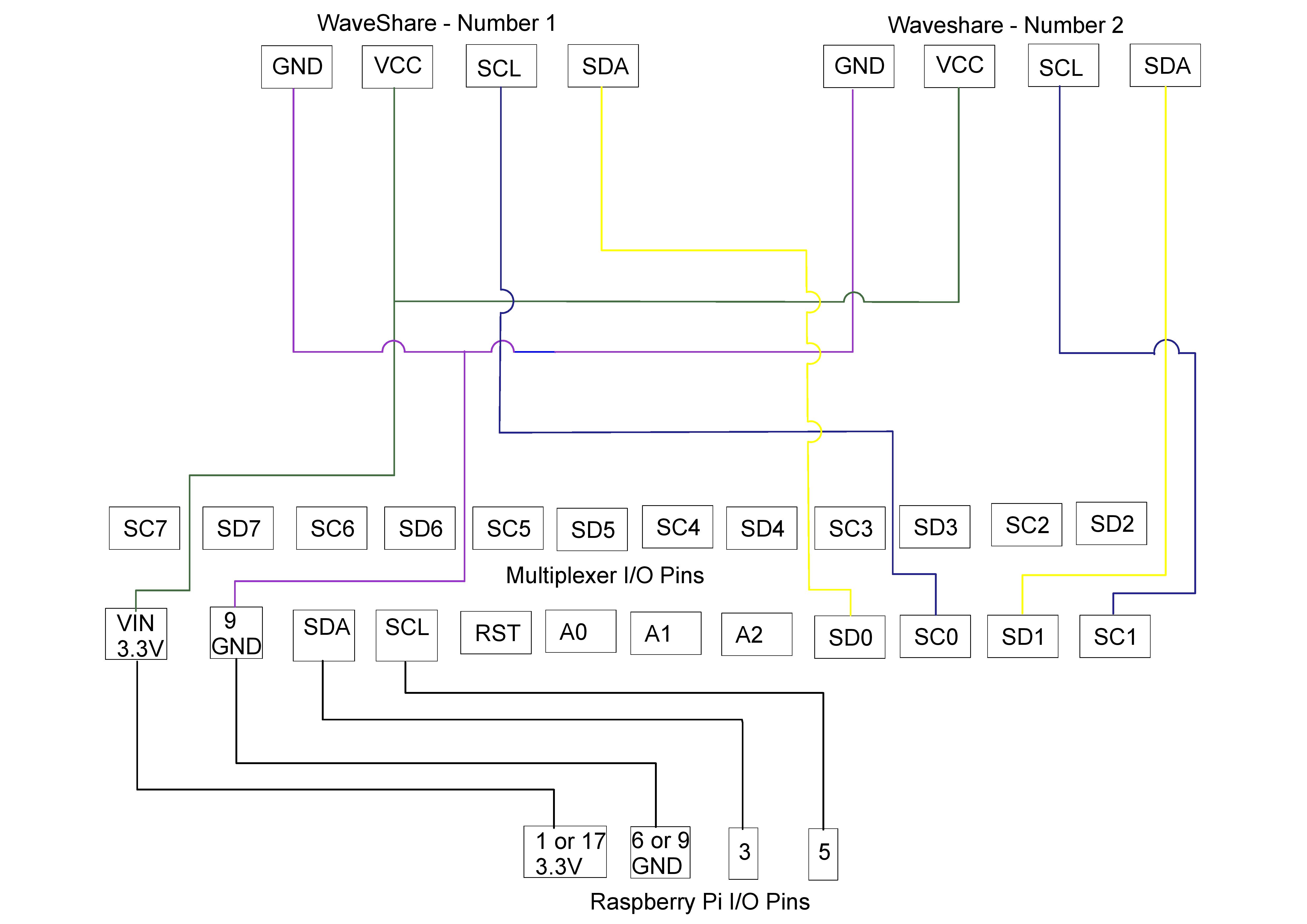 |
Whilst the diagram helps work out what goes where, there is another issue with trying to work out how to implement it with jumper leads. For the time being that side was being sidestepped as the delivery of some shorter jumpers with the correct connections was awaited. The jumper leads soon arrived and an attempt was made to wire up the screens. It immediately became obvious that the new jumper leads were not needed as the screens had four pin sockets and were provided with coloured rats tail leads that had no end fittings. That was fine for Wago connections but meant that all the jumpers would need to be socketed at one end and just wire at the other.
There followed a quite long period of interactions with Deep Seek, and tests by the score. All these resulted in nothing happening as planned. Eventually all the jumpers were removed and the role and function of each lead plus its position on the Pi 'hedgehog' were re-examined. With a minimum of wires the Multiplexer was queried one more time and its address was successfully reported. That proved that I2C was actually working and that the device had not been 'cooked' by incorrect wiring. The next step was to check the reported function of each pin on the PI 5 and then cross reference that to the wiring diagram. This identified that SDA and SCL were incorrectly wired. With that corrected and just a single screen the basic print test was run again and was successful.
With that done Deep Seek urged the connection of the second screen and offered an edited basic test script. That task was completed and the script was run. Happily both screens responded. With that news reported to Deep Seek, it was no time before an adapted copy of the thermocouples Python script was provided. This reads the results from the thermocouples every 30 seconds and then prints the results with each thermocouple being allocated a separate screen. The script was run and the program reported the temperature of each thermocouple exactly as planned.
With the thermocouples and the screens now working the only task remaining on this area was to add in some code to enable the thermocouples to be calibrated. Since time on that day was short, the task was postponed for the future.