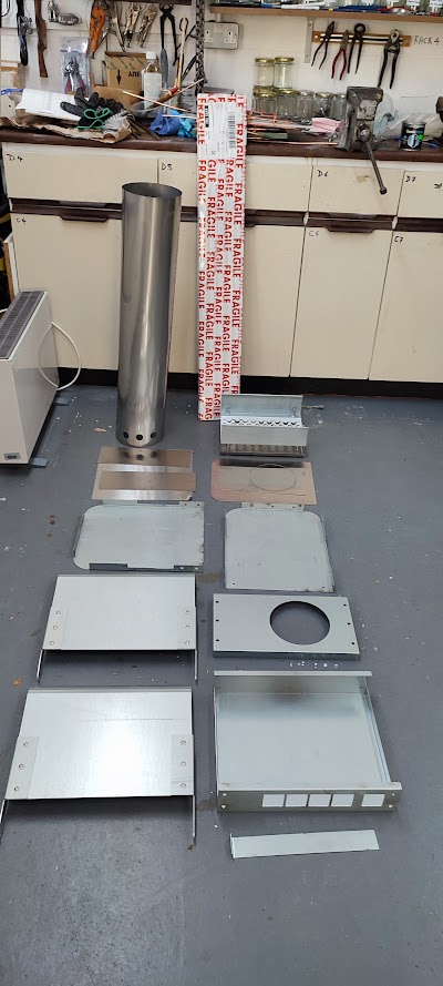
Next up came the fitting of the doors. In my head I was sure that I had drawn the holes for the door pivots in the end panels on the drawings sent to the Metal Men. However, the end panels had no such holes so it was necessary to work out where they should go. By this time the RivNut tool that I had ordered had arrived and it seemed sensible to make the holes in the end panel large enough to install the Rivnuts. The proposed pivot bolts were specified as 8mm and the matching Rivnut has an 11mm body. This caused some issues as I have a 10mm bit and a 12mm bit but nothing in between. What I should have done is to stop and chase up an 11mm bit from one of the local suppliers. However, impatience led me to make a start with 10mm which was a mistake. It quickly became apparent that the holes were not going just through the end panel, but also through the upstand flange of the base panel. Given the dimensions of the latter, it only required half a hole. Needless to say that was a recipe for wandering holes and inaccuracy, not to mention the extra work to manually file the final hole out to 11mm. A more sensible approach would have been to make cutouts in the base panel upstand flange and then the hole in the end panel should have run straight.
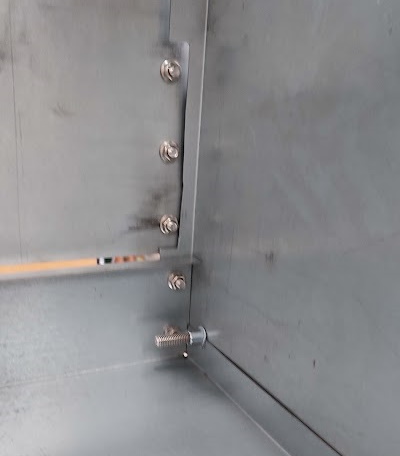
Although the assembly holes on the drawings were 8mm it seemed sensible to use 6mm bolts with locknuts as that allowed for a degree of 'flexing' to get parts in the correct place. The inital fixing seemed to be good until the doors were added and those wanted to spring out of place with suggested a lack of symetry somewhere. Given that it was all going to need to be dismanteled to fit the insulation It seemed sensible to stop and go back to that task.
However, as a bit of a diversion the brass trim for the funnel top seemed a good small job to chase. Having done a fair bit of riveting with brass rivets for a Tich miniature locomotive (still not finished) I felt confident that this job would hold no terrors. In practice I was wrong. Getting the rivets cut to the right length that would ensure that they would sqush down rather than bend over was not easy. The job was done in the end but the quality desired is not present.
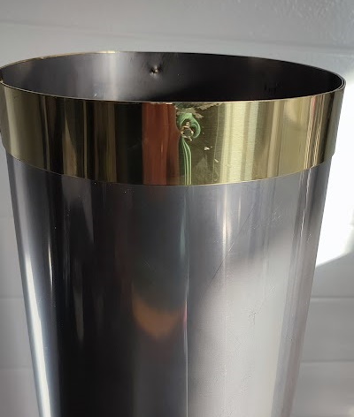
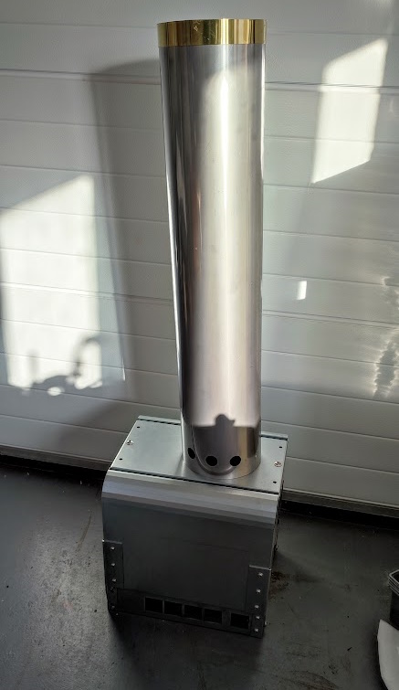
Happily, seen from afar the effect is not too bad as the photo below suggests. However, the photo is relly a 'mock up' since the boiler casing is missing the funnel stub which actually locates the funnel outer casing. That component is still awaited from our local engineering works.
In the mean time work has been started on the insulation and the insulation protection panels. The panels are just thin stainless steel which are designed to form a sandwich with the various casing panels. The protection panels are first located on the given casing panel and secured with engineers clamps. The four or so fixing points are then marked up and then the two pieces of metal are drilled through at 3mm. The protection panel and casing panel are marked to ensure that they will match later and then the holes in the protection panels are dilled out to 4.9mm. With that done it is possible to use the Rivnut tool to install the 3mm Rivnuts into the 4.9mm holes. There is a temptation to apply too much force which does not improve the compression of the Rivnut but does tend to bend the applicator. There is an adjustable stop bolt but I have yet to find the best way to set that. My suspicion is that I should go back to a fixed Rivnut and use that as a guide. The 25mm X M3 bolts are then applied to the holes in the casing and pushed through the insulation. The protection panel is then located on top and the nuts screwed up pulling the protection panel into place. The final stage is the addition of a lock nut to ensure that any vibration in active use does not lead to the plain nuts coming undone.
Unfortunately, this job is not quite as satisfying as it should be because the front end panel insulation is to be pierced by the joint beteween the upper and lower evaporation coils. Similarly the rear end panel's insulation will be piereced by the final stage steam pipe as it exits the casing heading for the manifold. The feed water tube will also need to be tucked under the rear panel insulation as it makes its way towards the funnel stub for pre-heating. Hopefully the fire doors and the casing base panel insulation will go on and stay put without too much further manipulation.
April Fools Day and a chance to slope off to the Garage. It was decided that the task for the day was to get the end panel hinge bolts problem sorted out while the whole casing was back in pieces. 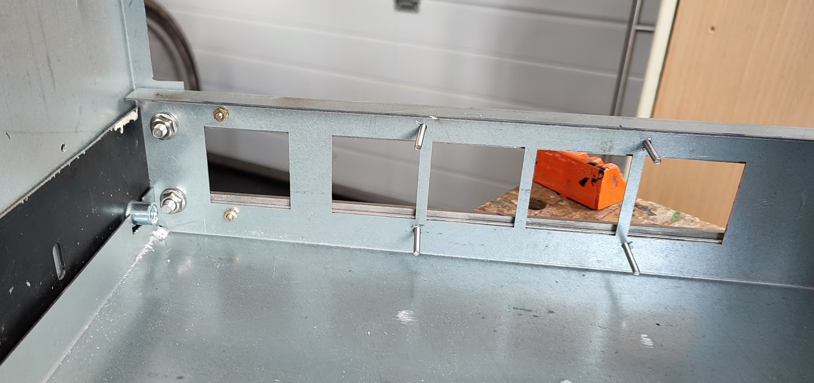 The first task was to cut clearance holes in the base panel updstand for the hinge pin Rivnuts. (See picture) That was easy enough to do as the ragged holes from the first attempt were clear. With that done it seemed sensible to examine the Rivnuts in the end panels and see which ones were closest to being correctly located. The rear panel seemed to have the rivnuts equally positioned so that was taken as the datum from which to work. The Rivnuts in the other end panel were removed with some difficulty and some re-cycled steel sheet was cut to make a 'cover panel'. The two end panels were laid back to pack with the repair strip in the panel with no Rivnuts. All the parts were carefully lined up and then clamped firmly with engineers clamps. The 'assembly was carefully turned over, checked for alignment and then clamped to the top of the Workmate. A dig through my collection of HSS drills eventually yielded on that was a tight fit into the the threaded core of the 8mm Rivnut. It was then sharpened carefully and. using the cordless drill, it was used to mark the repair plate but only briefly to avoid damaging the Rivnut thread.
Making sure that the repair plate's alignment was marked up on the end panel, it was then removed to the Mill and the two marks were turned into pilot holes and then enlarged to 11mm. The ordered 11mm drill had arrived by then. The repair plate was clamped back onto the end panel and the holes in the panel were adjusted to match the new holes in the repair plate. Finally two new Rivnuts were installed in the holes which helped to lock the repair plate into position. All four Rivnuts were then cleaned out with the 8mm tap to remove any damage from the various installation activities. With that done the end panels were re-fitted to the base panel and checked for square. Next up was a test of a door. 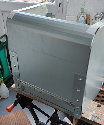 This was positioned, the 8mm bolts screwed home and then some tweeking of the hinge bolts was done. Basically they were not parallel to the sides of the front and rear panel. With that done it was found that the door was a perfect fit.
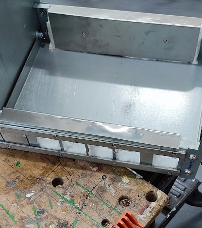
With that done the doors were removed again and some work was put into the insulation protection sheets. These are just thin stainless steel panels which are lightly secured over the insulation to protect it from abrasion. The side opposite to the damper holes was very easy to do but the damper side was not. In the end it was decided that as there was very little metal for new fixing holes some of the damper slider rail fixing holes would have to do two jobs (See picture above). That could have been simple but the insulation protection screws are flat round headed items while the damper slider scres are cross head counter sunk screws. Having no long M3 screws it was decided that the four holes in the securing plate for the damper slider would be 'flattened somewhat in the Mill. Since the screw heads were larger than the flute they had to be stuck in the lathe and turned down a bit. Eventually they fitted without protruding unnecessarily. The insulation was then applied and the long screws located in their corresponding Rivnuts. The result was rather less than perfect, but it should do,
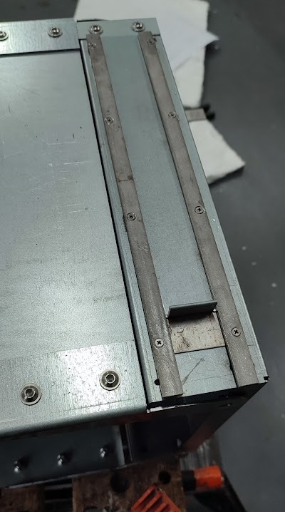 Happily that too opened and closed as planned without snagging.