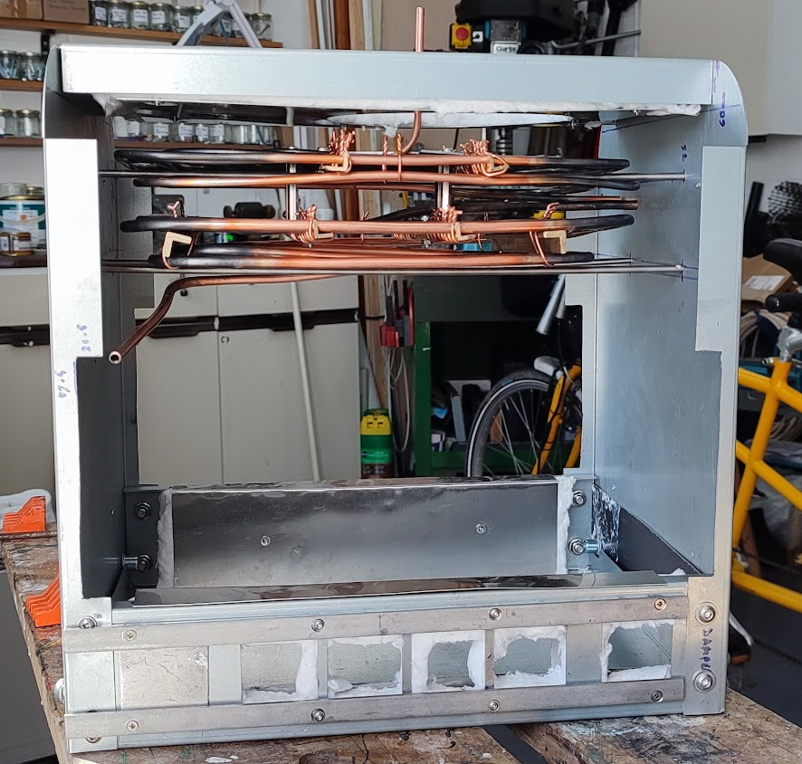
27th April 2024 - More Assembly
As was flagged in the previous report the end panels need to be drilled for the steam output pipe and the end panel insulation needs cutting at the other end for the connectors joining the upper and lower evaporation coils. The first step in that saga seemed to be getting the two coils joined into a single unit. The first issue encountered was that the 'extra' coils that had been added to use up the available pipe were 'loose and floppy'. A couple of extra cross bars in brass were added and the extra coils were tied down with copper wire. Next up was to fill in the 'hole' in the centre of the coils which was the zone that was below the safe bending radius of the cunifer pipe. Some scrap sheet metal was found and marked up. It was realised that it would be possible to bolt these capping or baffle panels to the brass angle that was holding the coils in shape.
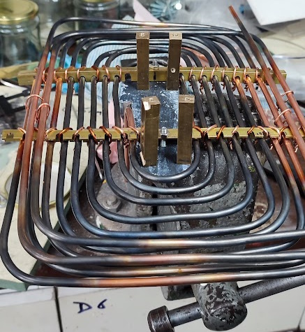 |
With that done it was realised that the two coils needed to be joined into a single firm unit. Much head scratching was done and then it was realised that some screwed 'standoff' pillars would be the answer. Whilst these are widely available on eBay I wanted to do the job 'now'. Thus some rectangular bar from the non-ferrous scrap box was cut to a bit over 50mm and then tapped at both ends M4. One baffle was marked and drilled and then the two coils were put together and the holes were copied onto the other baffle. That was also drilled and the four pillars were secured.
Persuading the four pillars to align for the second baffle required some nudging as the first baffle was not perfectly flat and the copying of the hole positions was probably not perfect either. Anyway, it was possible to get all four pillars securely screwed down making the two coils into a sold single unit.
It was at this point some thought was given to the pipe join between the top coil and the bottom coil and the also outlet pipe alignment. The pipes to be joined had already been trimmed, perhaps prematurely, but it was possible to hold the coils unit on the top of the casing to look at its horizontal alignment. It was immediately apparent that the output pipe was aligned to exit the casing directly in line with the proposed position of the manifold whereas I had expected it to exit at the other end of the rear panel. I must have done early tests with the bottom coil upside down. A possible solution to that was to add yet another right angled pipe turn to take the pipe to the 'right place' and then another bend to bring it back towards the manifold as originally planned. Fortunately there appeared to be sufficient excess pipe for that to be possible.
With the previous full sized steam launch early steaming activity was with composite logs and steam would be raised in no time. However, one did need to keep the fire stoked to keep the pressure up. An SBA colleague brought a couple of bags of 'Smokeless' coal and filled the bunkers as he thought it would be better. Certainly when that stuff was alight it gave out a great deal of heat and kept going for a long time. However, it was not too long before it seemed to take far too long to get up steam and keeping up pressure seemed more like hard work. Unfortunately what I had not realised was that smokeless coal is a misnomer. What the coal was doing was coating the tubes with a thick layer of soot. What I should have done is to brush down the tubes after every firing. Clearly a lesson to learn and for which provision should be made in the new boiler.
Looking at the coils it seemed as if they were set far too far apart. Obviously there ought to be room for inserting a flue brush to clean out the soot but the approximate 40mm of space did not feel right. As the pillars were around 50mm in length it seemed logical to cut them in half and thus reduce the gap to perhaps 15mm. That was a mistake as the short pillars brought the two coils way too close to each other
At this point it seemed sensible to head back to the CAD drawing board and explore what would be sensible.
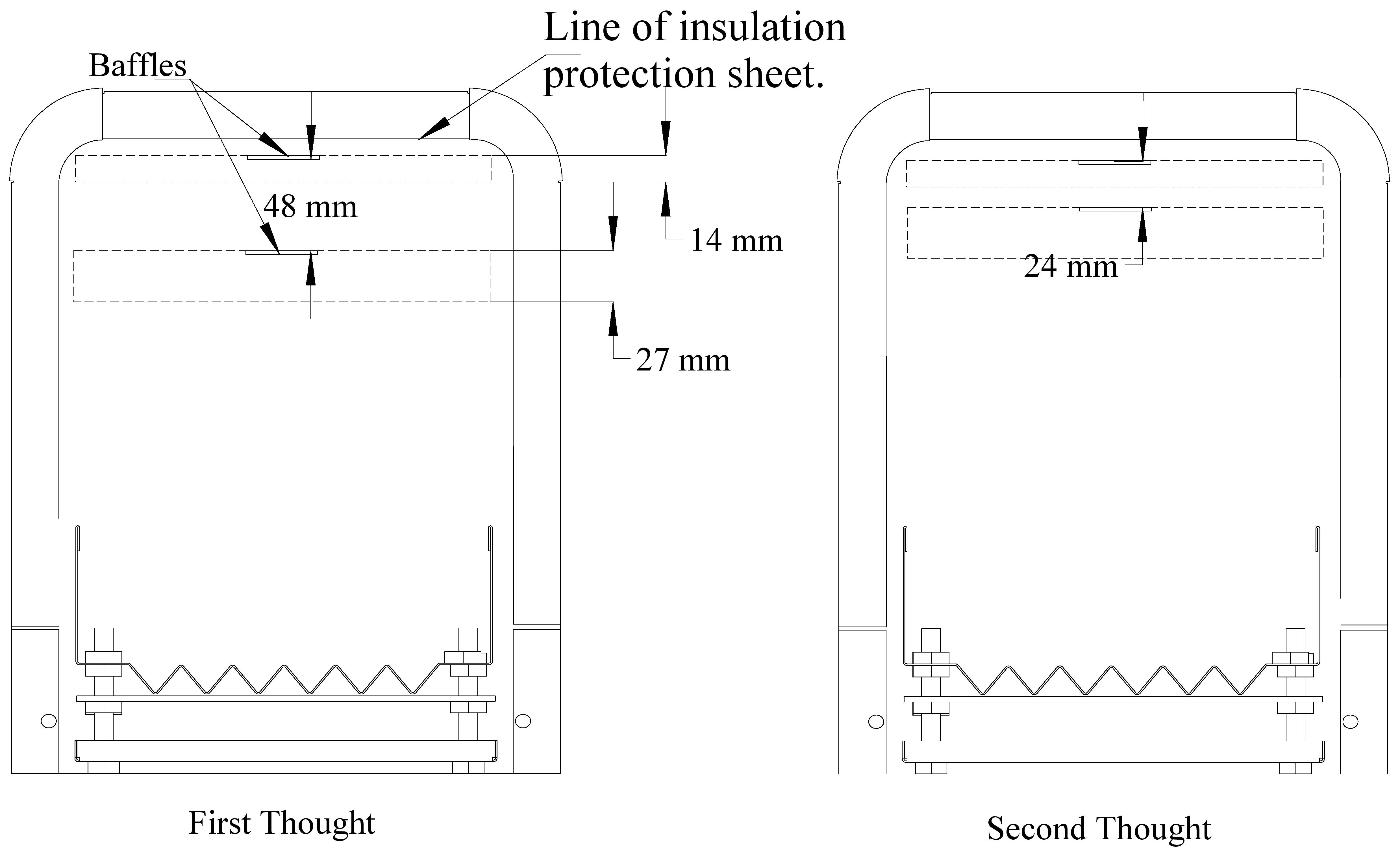
The First Thoughts picture shows the coils with the long pillars and the joined coils placed as high as possible. Obviously no room for a flue brush above the top coil so that would not do.
The Second Thoughts picture shows the coils with the shorter pillars placed slightly lower, but it is obviously not a good outcome. A flue brush would not fit either above or between the coils.
Clearly Third Thoughts were required to ensure that the flue brish could easily fit between and above the coils. That, of course, necesitated a visit to eBay in search of ready made pillars. The likely outcome with 30mm pillars is shown in the Third Thoughts illustration.
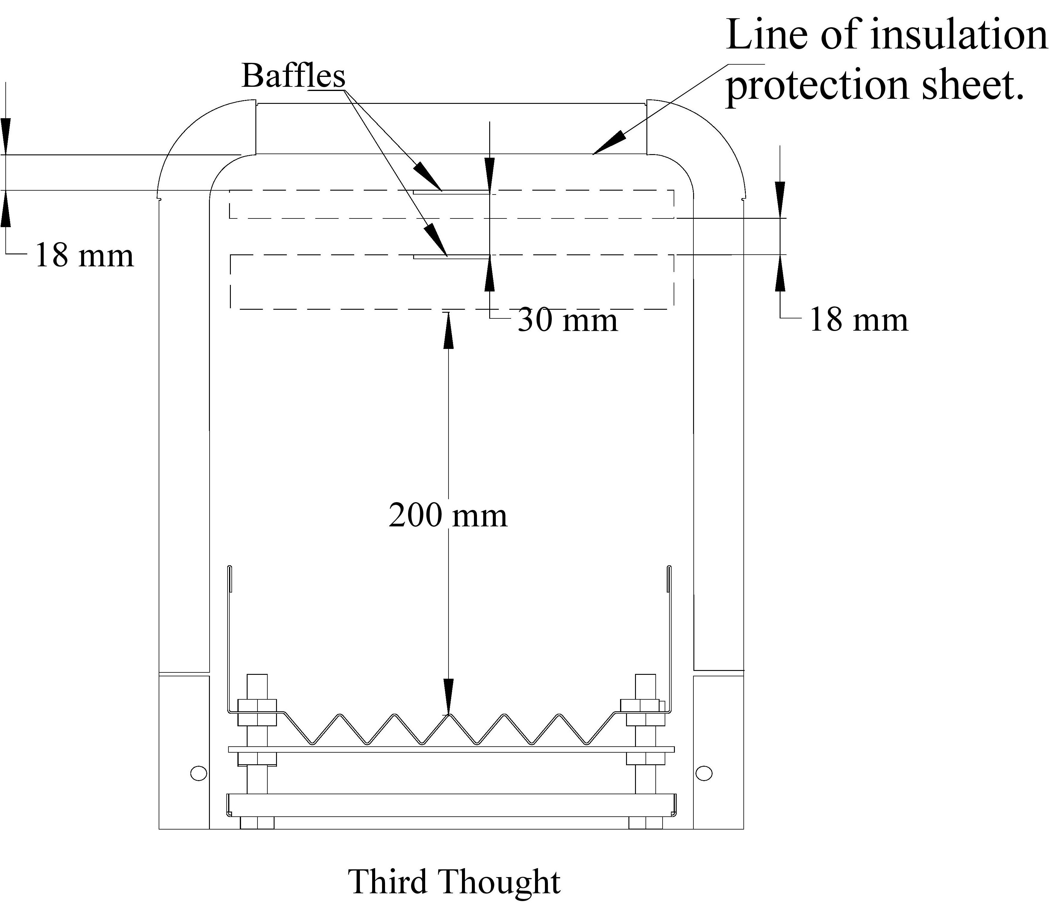
With this alignment there should be 18mm for the brush above the coils and 18mm between them. Additionally, with the coils unit positioned at this height there should be 200mm (7.9") of combustion space for the fire. This exceeds the SBA's recommendation of a minimum of 152 mm (6") above the grate for good combustion in a small boiler.
With that bit of planning done the next step was to work out the alignment of the rods on which the coils unit will sit. There will be two pairs. One pair under the top coil and one pair under the bottom coil.
With all the theory summarised on a print out the next step was to make contact with reality. The first hiccup was to discover that the size of pillar that I wanted was generally not available at the time from UK suppliers. Thus I went for the next size up with the possibility of cutting down if necessary. In practice it turned out that the available 40mm pillars were satisfactory but perhaps 45 mm might have been better.
The casing top panel with its insulation and insulation protection panel in place was put on the top of the casing but not secured. The casing was then turned upside down and some pieces of wood scrap were gathered.
The gap above the coils was notionally 18mm so 20mm PAR timber and some MDF provided the spacing equivalent. The joined coils were placed on top and the result looked reasonable. However, the planar irregularity of the coils became very obvious at this stage. It was then time to get some lengths of steel rod, insert them into the coils and then mark the end panels with where a through rod in the same position would exit the casing. This should have been an easy job but getting the rods to lie wher I wanted was difficult.
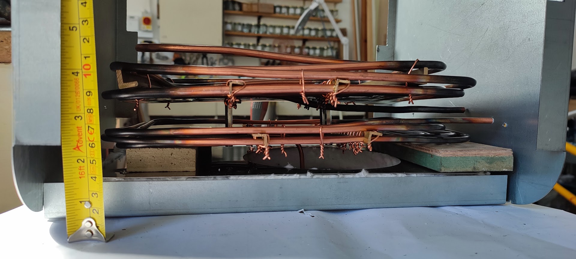 What I should have done is to cut the actual Stainless rods that will be used to length and then fit them diagonally. They could then have been left in place when satisfactory positioning had been found. In practice I used some scrap rods which were shorter. With a few tests with the flue brush and much marking with felt tip pens, it soon became time to take out the coils.
The next task was to make sense of the markings. I was surprised by the extent to which there was horizontality on each of the end panels. Another piece of MDF scrap provided a panel wide ruler and with the aid of a set quare the horizontal lines were marked up fully. The spaces between the lines was measured and marked and the 'theory' print out updated. Although the test ensured that the top coil was parallel with the top panel, the variability in the coil meant that the bottom line on one end panel was 10mm lower than the other.
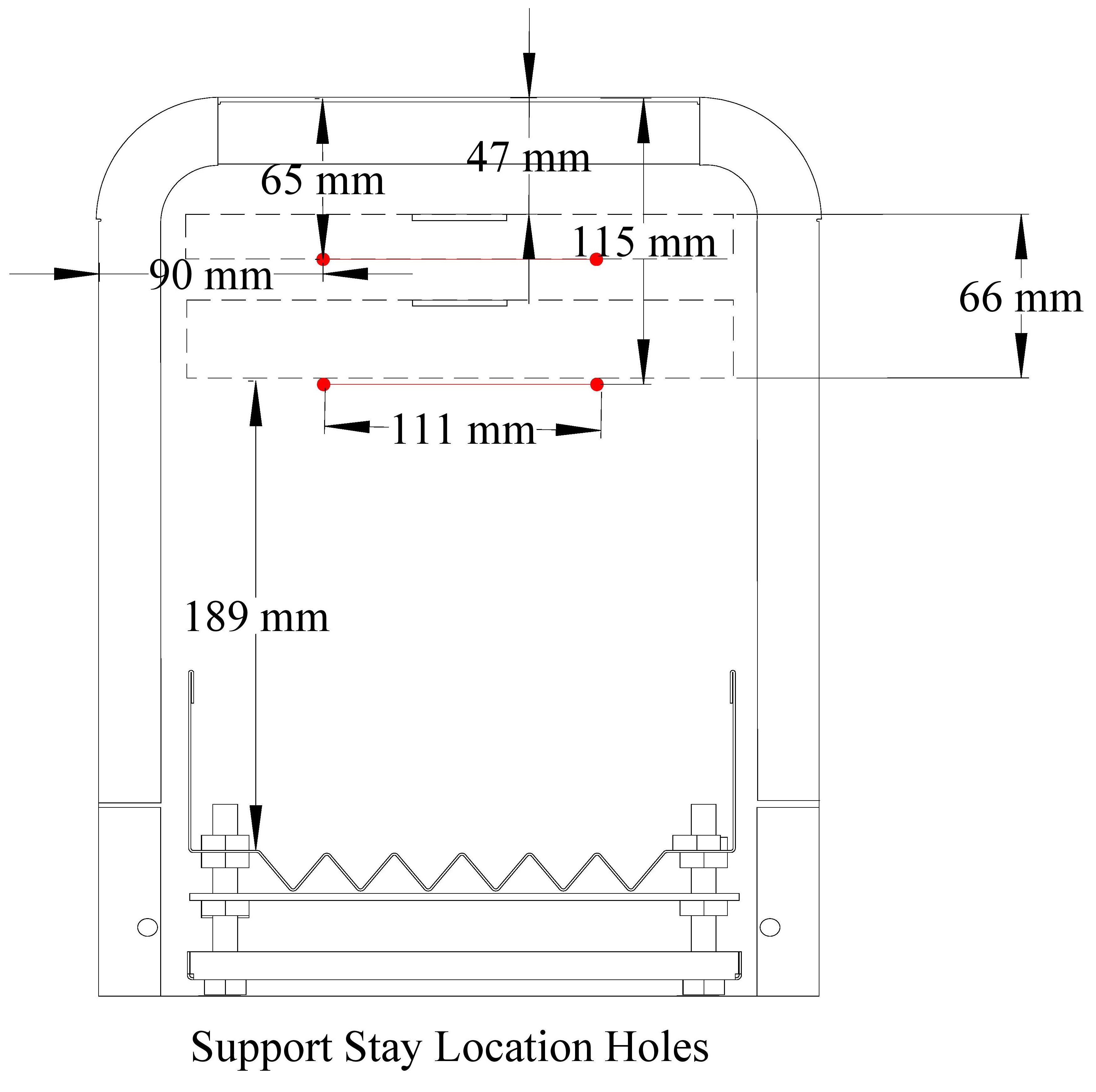 |
It seemed sensible to accept that difference and so the horizontal lines were marked up with the position of the holes (90mm from the outside edge). Drilling the holes for the support rods was soon done and the holes cleaned up. The stainess support rods were cut to length and then with the casing top in position and the whole casing up side down it was fairly easy to align them through the coils and finally fit their cap nuts.
The whole assembly was then turned over and a final flue brush test carried out. That seemed to be satisfactory which suggested that it was probably time to stop.