At this stage the reader is probably wondering when the casing will be completed. The same feeling has dogged the builder as so many things seem to require the casing to be in pieces not fully assembled. A key missing element has been the funnel stub which was off site with a local enginering company to make a new inner funnel with larger clearance (my design mistake). That was delivered at the works in January and accepted on the basis of a three month delivery time. At the end of that time it was not ready and various promises of "Next week without fail" were received. That went on for another three months until it was clear that the job would never be done. The parts were collected, an order sent to the firm that originally made the funnel parts and the replacement was back in about three weeks.
With the funnel stub returned it was possible to attach it to the top panel and then sort out the insulation and insulation protection panel fixings. However those will have to come off again as a route is needed for the whistle supply pipe and for the feed water pipe to the pre-heater in the funnel. Time wise there was a big diversion into seeking a whistle and then researching whistle building. Material had been ordered to make a whistle which arrived in the UK from China, cleared Customes and then disappeared. A refund has been issued but that hiccup put the whistle back to the starting line again. The material was re-ordered and arrived within a week. One feels somewhat embarassed by that kind of service as it means the product must have come by air giving it a terrible carbon footprint.
Happily, a promise was made of a whistle valve design for amateur construction. That was received and work put into drawing it in CAD. Whilst it was clear that the design would work, it did rather look as if it would seriously constrict the steam flow, not to mention pushing my macining skills to the limit. Meanwhile research into steam whistle building turned up a US based steam model railway magazine with two useful articles on making whistles. One of them showed how to use a simple stainless steel ball valve with a quadrant and spring as the whistle valve. Very cheap and very simple so that is now in the plan.
In the background the design for the manifold was completed and then materials ordered. The original plan was to make it out of mild steel, but a friend suggested that brass would perhaps be nicer. Given my confidence in my machining skills it seemed sensible to acquire both a piece of steel and a piece of brass and then work on both at the same time. Thus if a catastophe occurred it would not be a case of going back right to the start but of picking up the other manifold and being careful to avoid the catastrophic step on that one.
As so often with these things the design went through several iterations and finally ended up in the format shown below:
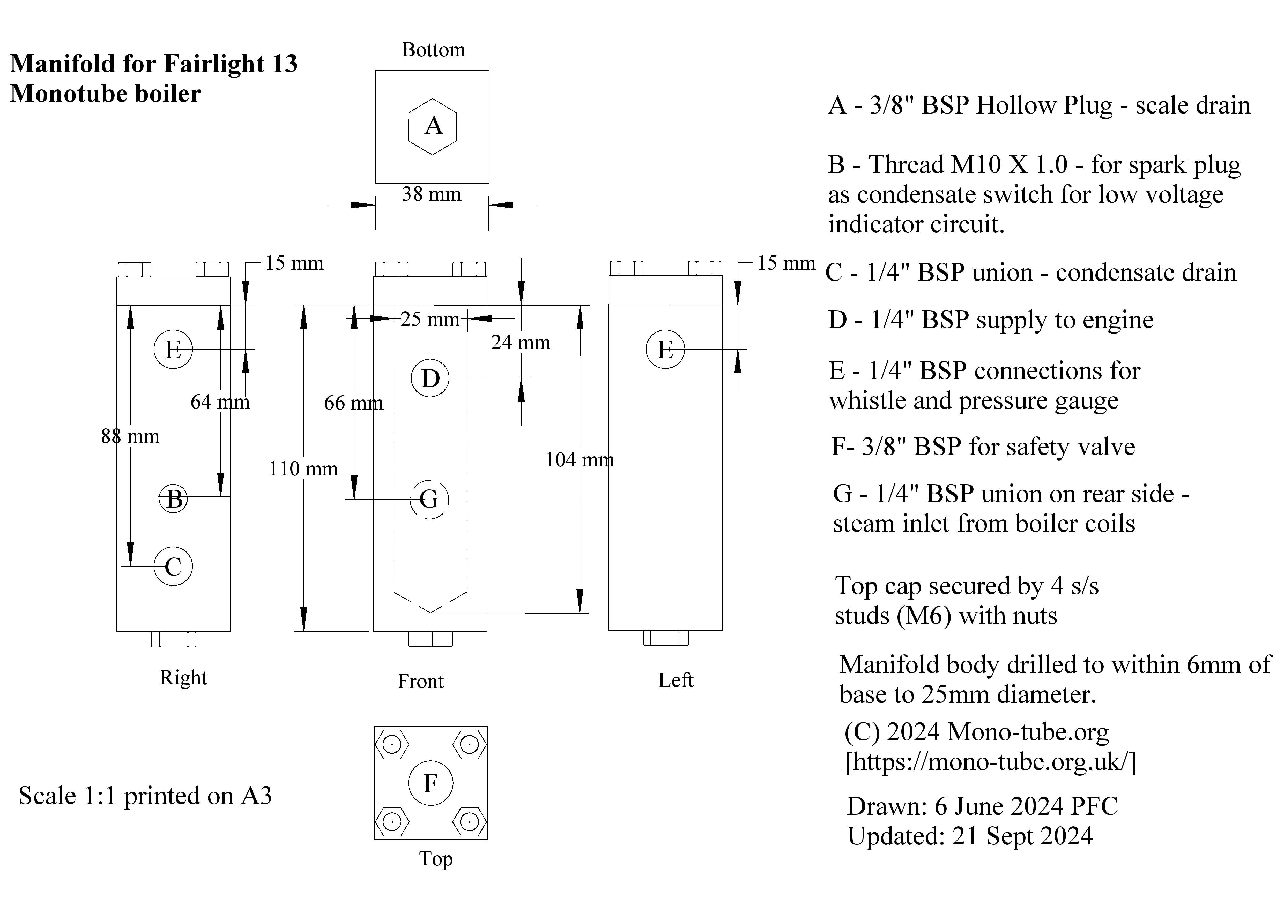
Steam from the coil enters the manifold from the rear. The port at the very bottom is 3/8" BSP and is fitted with a hollow plug to catch any sediment and solids that blow through the coil. On the right there is the condensate drain that leads to a valve and hence the hotwell. Above that on the right is the spark plug which is the switch in the circuit that provides a warning light to empty off the condensate. On the right is the steam take off that leads to the whistle, separately isolated, and on the left a port for the pressure gauge also separately isolated. Finally, the front contains the port that leads to the engine through a globe valve.
Creating the manifold was far more difficult than had been expected. The centres of each piece were set up in the milling machine which has DRO making for excellent accuracy. For drilling the 25mm hole down the centre the part was shifted to the lathe. Given that the material was square in section the self centering four jaw chuck was used. After a certain amount of work it was clear that the part was determined not to run true and instead ran with a small wobble. Having milled the ends of the material it seemed pretty certain that the material was square in the chuck. Eyeballing the chuck it was clear that the base plate was running true so it was 'obvious' that the chuck jaws were not coming together exactly in the centre.
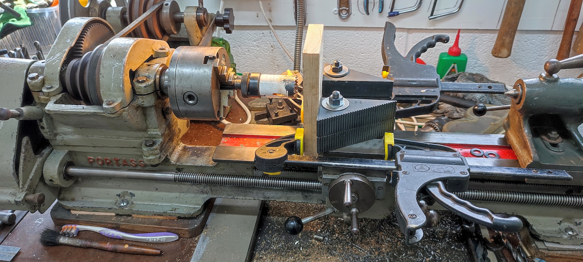
A friend offered a quick(ish) solution which was to use a fixed steady for which I would need to turn down a short distance of the square section bar to circular. Not having a fixed steady, I was lucky enough to see a suggestion in a discussion forum of making an 'emergency' one out of wood. This I did and cut a hole in it to match the turned down part of the bar. Actually, the hole was cut first and then the bar turned down to fit. The latter was not a pleasant task at all. Getting the 'feet' for the steady was not too difficult as my woodworking is far better than my metal working.
 |
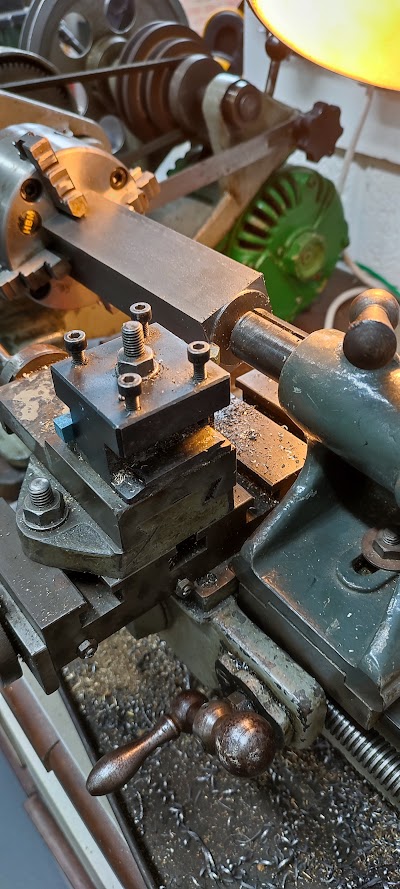
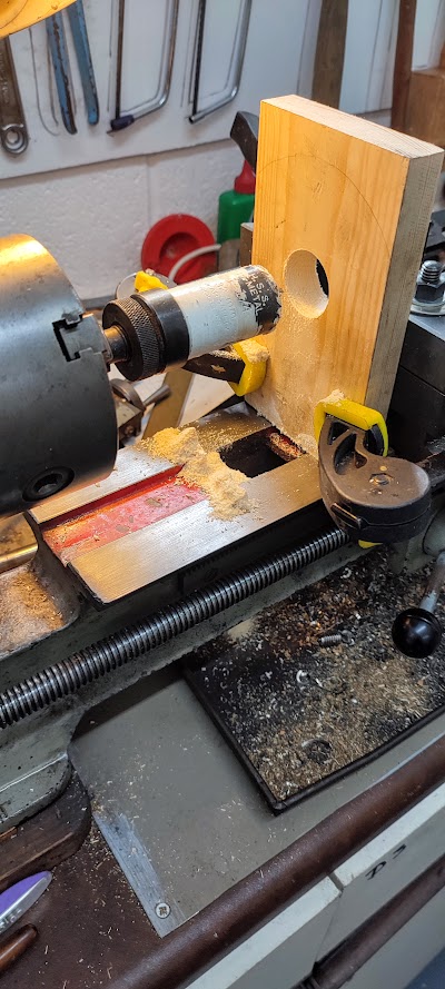
With steady in place and regularly supplied with oil the wobble was minimsed and drilling proceeded slowly. Many of the drills I had which appeared to be nice and sharp did not perform well so I spent a long time re-grinding them on the bench grinder. It was only when the main hole was nearing completion that I stumbled across a piece in one of the model engineering forums discussing drilling steel and drilling brass. Apparently drills need to be set rather differently for steel than they do for brass. With that discovery made drilling progress was somewhat quicker, but more time was spent with the bench grinder.
 |
It was also at this point that I did what I should have done when the wobble was first spotted.
 |
I dug out the Test Dial Indicator and applied it to the chuck backing plate. That recorded zero wobble which was not unexpected. I was then wondering how to work out the degree to which the chuck jaws were off centre and for no good reason moved the TDI to the chuck body. Oops! Here was the wobble easily measured in hundredths of a millimeter. The base and body were soon separated and the digital caliper indicated that the stub on the base was just slightly smaller than the 'hole' on the base of the chuck. The answer was to re-machine the stub on the base plate just a little bit larger. Not having DRO on the Imperial lathe, and having always worked in MM, the solution seemed to be to use the go/no go approach taking off miniscule amounts at a time. Eventually a very tight fit was achieved and the bolts were screwed home. For a test a drill was fitted into the chuck and then spun. It looked as if the wobble had been completely removed.
Thus eventually the steel and the brass manifold bodies reached completion of the central core. Next up was to cut off the rounded section that was made for the steady, adjust them to the correct length and finally mill the ends flat and square. With that done the task moved to drilling and tapping the various ports that are shown in the diagram up the page.
The observant reader will have spotted that the manifold has two 3/8" BSP ports, six 1/4" BSP ports and one M10 fine port, not to mention the four holes for the studs that secure the cap. It looked like a lot of work for the mill in drilling mode. The 3/8" ports needed a final drill of 15.25mm before threading. There was nothing of that size in my collection which meant a new one needed to be purchased. Much scouring the Internet led to the purchase being made from Drill-Force which turned out to be a Chinese firm. The products looked good and the price was reasonable and the dill soon arrived. Unfortunately, I quickly discovered that there was a problem. None of the drilling chucks in the workshop could cope with such a 'fat' drill.
With that problem ahead more time was spent on the Internet looking for reduced shank (blacksmith) drills of 15.25mm diameter. My efforts suggest that such a product does not exist. There were plenty of 15mm and 15.5mm drills but nothing in the middle. I then sought advice on whether to drill at 15mm or 15.5mm. It was suggested that 15mm would be almost impossible to tap especially by hand in the steel version, whereas 15.5 would result in a 'slack' fit with low surface contact which is not what one requires for parts under steam pressure. Whilst this was going on, I parcelled up the drill and got it ready to return to the vendor as it had not been that long since it was received. To my surprise I found no return address so I contacted the firm through eBay's messaging system which is when I realised that the firm was in China. I received back a very nice message in excellent English that returns were not worthwhile as the shipping cost would be more than the drill had cost. I was asked to seek out an organisation/individual who could make use it and thus add to world happiness!
Whilst rummaging about in the cupboard under the lathe looking for something I came across a box marked 'vertical slide'. I had forgotten that the inherited lathe had come with this object but I had zero recollection of ever using it. Pulling it out of the box I found that it had an adjuster wheel and looked as if it secured with bolts into slots. It also came with a heavy angle plate which was something I had been promising to buy myself for ages. The tool post on the cross slide was quickly removed and the vertical slide secured in its place. A quick scan of the Internet showed that the vertical slide was used to do milling on the lathe. However, the light bulb moment was when I realised that I could mount the fat drill in the lathe chuck and the manifold in the vertical slide.
As a test the manifold cap was mounted in the vertical slide and the 12mm drill that had been used to make the preliminary hole in the cap was mounted in the chuck. Having no DRO on the lathe it was back to go/no go but very quickly the cap was aligned to slide onto the drill. The 12mm drill was soon replaced by the 15.25 drill and I soon had the correct hole for tapping the cap to 3/8" BSP. The tap was mounted in the chuck and, with the power off, a start was made on cutting the thread. Unfortunately, I probably applied too much 'down' pressure as the tap started to cut a hole rather than cut a thread. Everything was then moved to the mill and somewhat better progress was made. However I was under-impressed by the effectiveness of the eBay sourced tap. Given the importance of good threads it seemed sensible to look for another one and Tracey Tools turned up in the Google listing. A quick look at their website made it clear that they were specialists and something from them would probably be good.
Whilst both the eBay and the Tracey taps were taper taps, the Tracey product had a better shape and got straight to work. It also seemed a whole lot sharper than the eBay one and the 3/8" BSP ports were soon done. Moving on to the 1/4" BSP ports I found that I had the correct size in a multipack tap and die kit bought from Aldi some years previously. Its shape was identical to the Tracey tool and it had four flutes which made me optimistic about its performance. The vertical slide remained mounted in the lathe as I discovered that I had the 11.8mm drill that was required for the tapping hole. This was part of the lathe inheritance and was a very long Morse taper drill originally designed for use in the Tailstock. However, this was happily swallowed by the lathe chuck and applied to all the ports. The latter were carefully positioned on the mill with the DRO, started with a centre drill and then pre-drilled with something larger. That drill was then shifted to the lathe along with the manifold and the go/no go routine got things aligned.
For getting the ports in the right place a couple of parallels were created to raise the manifold body to the 'right' height in the lathe vice. The angle plate and some other fixings were used to provide a 'stop' for the top of the manifold. Doing that required the angle plate which, given its age, was set up to Imperial measurements, to be re-milled so that the slots were longer and were also the same width as the slots on the milling machine table. The horizontal manifold then had the top right corner found with a wobbler and the DRO was set to zero. This set up was left on the mill as both the brass and the steel manifolds were the same size (give or take the odd millimeter) and thus it was not necessary to keep finding the origin point.
The process of doing the rest of the ports became pretty routine and extended over a couple of weeks. A similar approach to positioning, drilling and tapping was used for the holes in the top of the manifolds. The studs had been ordered early and when it was time to use them it was found that they had not sent the right version. Thus a new set had to be ordered which was tapped to the correct depth but it was later found that one stud in the set had come in only tapped at one end. Happily this did not matter as ten had been ordered but only eight were required.
Eventually, the great day arrived when all the ports were completed and it was possible to consider the manifolds as 'finished'. Of course, such a consideration was incorrect as there was the fitting of the bracket to attach the manifold to the rear of the casing. The bracket was a substantial stainless object from a pack bought some years previously. This was carefully measured and then drawn along with the manifold to sort out whee the screw points should be. In practice it was found that the measuring had not been that good so a first hole position that was near the side of the manifold was centre drilled and then drilled and tapped. The bracket was then temporarily secured, carefully aligned, and the rest of the hole positions were found using the go/no go technique with the drill into the holes in the bracket.
With the bracket holes drilled and tapped and the fixing bolts chosen it really was time to say "the manifolds are finished".