29th March 2026 - Back on Track
29th March 2026 - Back on Track
A very wet and windy Sunday in Cymru has been an excuse to duck the unfinished garden jobs and settle in the study. The objective of the session is to re-wire the two MAX 6675 boards that will interpret the voltage signal from the two thermocouples. The problem previously faced was that the jumper cables provided with the boards looked useful, but were in fact rather low quality items. The regular clipping onto the boards and then un-clipping to correct mistakes soon had the sockets becoming slack. In between fighting with the Pi, as explained above, two sets of Jerky Jumpers from Pimoroni were purchased. One set was with sockets at each end while the other was with sockets and one end and pins at the other. These were both longer and much better quality items than those that came with the Boards.
Whilst at it, a search was made for different clip down wire connectors. The Wago 221 connectors I had purchased were good at making strong connections between wires quickly, but they were set up such that both wires went onto the clip from the same side. That made for some awkward cable runs. What I needed was a small clip of that type that would allow a cables to go in at one end and 'out' at the other. What I did not know at the time is that Wago's 221 series also includes an 'inline' clip which is exactly what I was seeking. A rather larger quantity than was needed were soon purchased via eBay at a reasonable price and it looked as if everything needed was to hand.
The other important item was the wiring diagram that had been supplied by whichever AI system I was using when I enquired about how to wire the MAX 6675s to the Pi. This has been useful, but was not actually correct when first used. However, the amended version was pinned up and everything was ready.
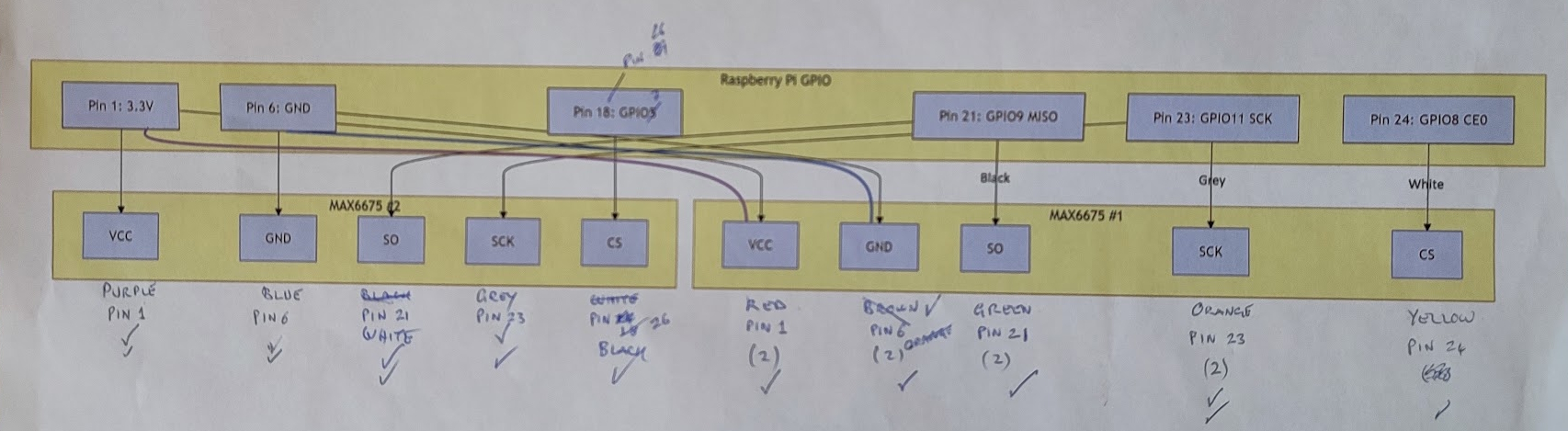 |
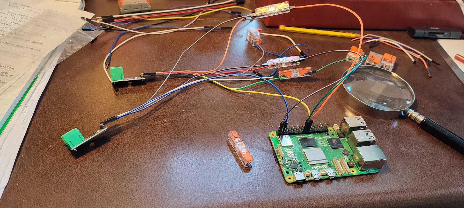
It was soon discovered that the new Wago clip connectors could not cope with two jumpers with pins on the end. A single pin terminated jumper or a single pin terminated jumper plus a stripped jumper wire would work but not the two pins. That mean four of the five connections would have to include a stripped wire. The solution was to select from the now 'rejected' jumpers four that we a good fit on the pins on the MAX6675 board. Fortunately that was achieved but it rather messed up the original plan to rationalise the wire colours. The 'linear' Wago clips made the wiring less of a 'Cats Cradle' and thus the wiring job was soon completed.
 |
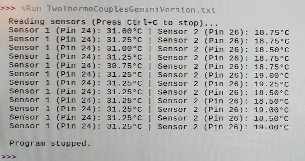 |
Next the Pi was connected up without its case to see if the new wiring was successful. Happily that was the case and the Python script ran and gave a nice display of temperatures from the two thermocouples. It was not noticed for a few moments that Sensor 1's readings were 12 degrees too high. A quick glance through the program to see where to put in the adjustment was a reminder that the last time Python was used seriously was nearly 10 years previously. The best place to slot in a correction factor was not immediately apparent.
No doubt that can be solved by uploading the program to Deep Seek with a request for assistance. Another test will be to swap the thermocouples over and see if the difference is from the different products. One sensor is a purchased item while the other is a 'free' object that was thrown into the package by the MAX6675 vendor. Having bought and used his/her product it looks as if using slightly higher quality jumper wires would have been better than the free gift.
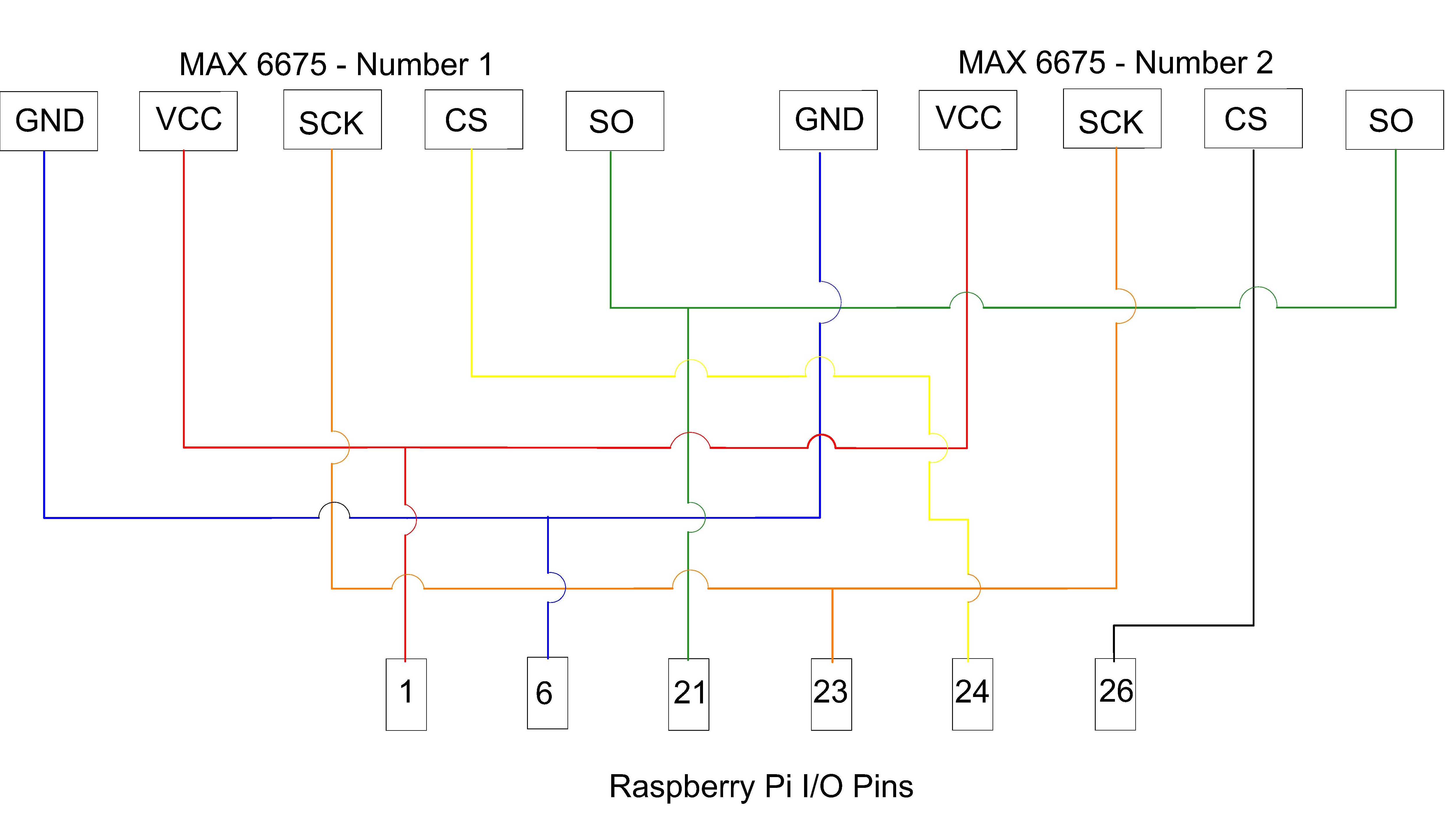
Having got thus far it seemed sensible to pause and make a good record of how the wiring had been installed. Initially it was thought that a photograph would be sufficient, but having taken one it was clear that a proper drawn diagram would be better. The MAX6675 boards do have their pins marked but the lettering is very small and not easy to see which is why the magnifying glass is on the desk.
Thus the CAD program was loaded and the diagram re-design was commenced. What was felt to be a simple job turned out to rather more complex as four of the five wires from each MAX6675 board needed to join before connecting to the Pi. Ultimately lots of the lines had to cross and the original colours were abandoned. This time a single colour was used for each 'strand', and has no significance in the interpretation of the diagram apart from allowing a 'route' to be identified.
 |
Having progressed this far, the next step will be to dig out the mini displays and their driver boards' It will then be time to engage in a 'conversation' with Deep Seek about the wiring and the edits to the program so as to display the readings on the mini displays.
Some thought also need to be given to how to control the electric motors that provide the feed water. There are two so that there is a back up in case of one failing. The feed water flow is not that simple as there needs to be a 'start up mode' with an initial pump though to fill the system with water. The pump must then stop. Of course that could be done manually and provide a test for the hand pump. The excess in the manifold at that point will need to be drained and then attention can be applied to lighting he fire. Once that is going and some steam is being generated the pump will need to re-engage in 'operation mode'. This suggests that a number of decisions need to be made about the control mechanism for the pumps besides the computer based system that will attempt to maintain operational equilibrium.