6th May 2024 - The fiddly bits and final insulation
6th May 2024 - The fiddly bits and final insulation
The first step towards insulating the front end panel was to remove it from the casing assembly and then attach the insulation protection panel. Given the earlier problem of over tightening the M3 Rivnuts it was found the the M3 bolts would not fully screw though the Rivnut. Thus step one was to re-tap the rivnuts so that the bolts would run free. With that done it was possible to screw the protection panel down tight against the end panel. The holes for the four support rods for the coils were then drilled into the protection panel using the end panel as a template. Next up was to re-fit the end panel, re-insert the support rails and then see where the top coil outlet and the bottom coil inlet touched the insulation protection panel. With those points marked the end panel had to be removed again, the insulation protection panel separated from it and attention paid to the pipe end markings. This was required because it was planned that the pipe fittings joining the two pipes would be kept on the outside of the insulation. This was also going to be where one of the thermocouples would be attached to the joined pipes to provide 'mid way' temperture information.
Holes for the two pipes were drilled and then the insulation protection panel was cut straight across from one hole to the next. At each hole a short cut above and below the hole was added. The idea was that the panel could be pushed over the connected pipes and then the flaps bent back flat again afterwards. It was a nice idea but it did not work. In the end the protection panel was secured to the mill table and the 'cut out' became a 'mill out'. With that done it was possible to check that the hole was the right size. With that correct it was possible to reassemble the end panel with its insulation and protection panel and then cut away the insulation where the short pipe joining the two coils would go.
Once done the position of the thermocouple was marked and a hole in the end panel drilled. This was turned into an oval sloping hole with a file drill so that it would carry out the thermocouple cable with no sharp edges to rub and wear the insulation. The thermocouple was attached to the joining pipe with copper wire as that seemed the simplest thing to do.
Next up was the steam supply pipe from the lower coil. This would plug into the manifold and supply the necessary steam. As wound the outlet pipe was quite low down and for ease in fitting other things it had been bent out towards the side. It seemed sensible to work out where it should be and that required some design work on the manifold. It also required some thinking about the vertical positioning of the manifold to facilitate the outlet pipe of the safety valve.
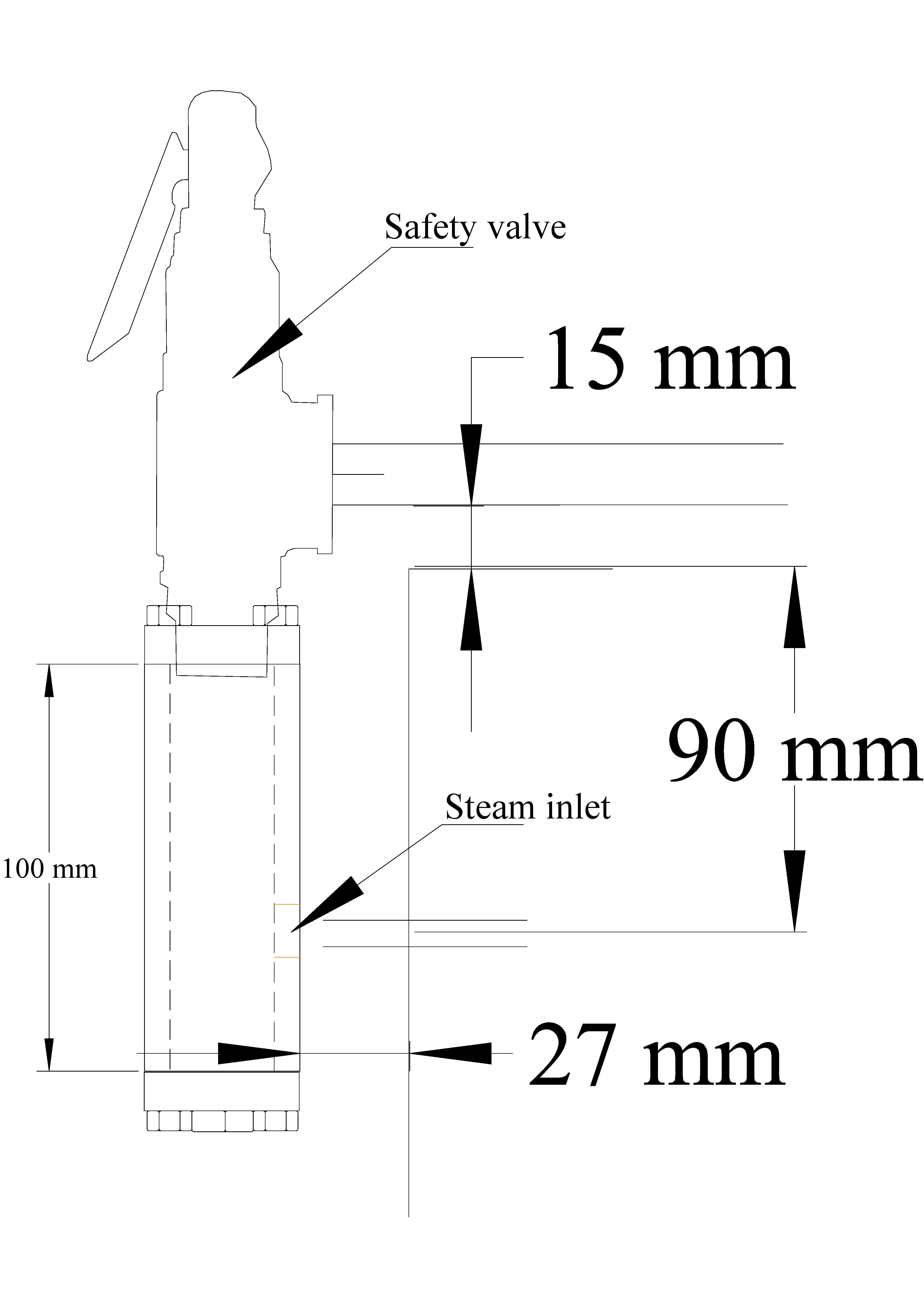 A tracing from the advertising material for the safety valve was made and scaled to full size then attached to the draft sketch of the manifold. A suggested 15mm OD outlet pipe was added, although that is probably rather too large bearing in mind that the steam inlet pipe has an area of something under 30 sq mm whereas the 15mm pipe has an area in the region of 175 sq mm. Thus the outlet is six times larger than necessary. A 10mm pipe might be better, but I do not have any of that in the useful odds and ends pile.
With those parameters identified it was necessary to see how much space would be required for the 1/4" BSP fitting that would connect the steam inlet pipe to the manifold. It was discovered that 27mm would be about the minimum clearance required. Finally, the last parameter was the clearance under the outlet pipe from the safety valve. Clearly the pipe should not be at the level of the top of the boiler casing but somewhat above it. Plucking a figure from the air, 15mm was chosen on the grounds that it would be sufficient room to enable spanners to be used on any nut on the outflow pipe without touching the casing. The last step was to measure from the centre of the inlet pipe to the top of the casing and the result was 90mm.
With that figure identified and the position of the pipe on the coil noted it seemed sensible to assume that the manifold would be located in the centre of the rear end panel and the hole for the steam pipe should be 90mm below the top of the casing.
The rear casing panel was soon marked up and the hole was drilled large enough for the 1/4" BSP nut to slip though. The only difficulty was that large diameter drills in thin metal can jam as the hole is nearly finished. The panel should have been secured on a wooden block for the drilling. With that lesson learned the hole though the insulation protection sheet was drilled with the end panel firmly held down on a piece of waste wood.
Having worked out where the outlet pipe should be the next task was to ensure that it actually ended up there. Of course, the 'proper engineer' reader will be thinking that one should have sorted all that out first before bending the coil. That would have been the correct approach but at the time the coil was prepared insufficient forward thinking had been done. Given that the pipe was 'near' but far from correct some extra pipe bending was done following careful annealing of the relevant length. As the photo shows the outcome was far from elegant, but the pipe has ended up in the correct position.
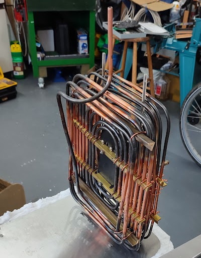 |
| Horrible bending |
However, the upward bend means that water will not naturally drain from the coil. Thus after use it will be necessary to gently heat the coil to evaporate the remaining water if rust is to be avoided.
With that done it was necessary to secure the rear end panel to the casing base, install the coils unit, get the insulation into position, fix the insulation protection panel with its four screws and insert a couple of support bars for the coils. Easy to write, but not a simple task as there was always something in the way. With that done the final support bars were installed and then attention was paid to the next stage; the manifold. In preparation for that the steam output pipe was cut back to length, its nut fitted and the cone soldered onto the end.