The first task was to create the base rectangles for the bending jigs which emulate the space into which the coils will be fitted. Next the core ‘sausages’ were created which are the spacers for the centre of the coil. This is an area where the bending radius would be below that possible for the available pipe. For simplicity the 20mm radius of the hand pipe bending tool was chosen. Both 3/16” and ¼” pipe can be bent below this but not by very much.
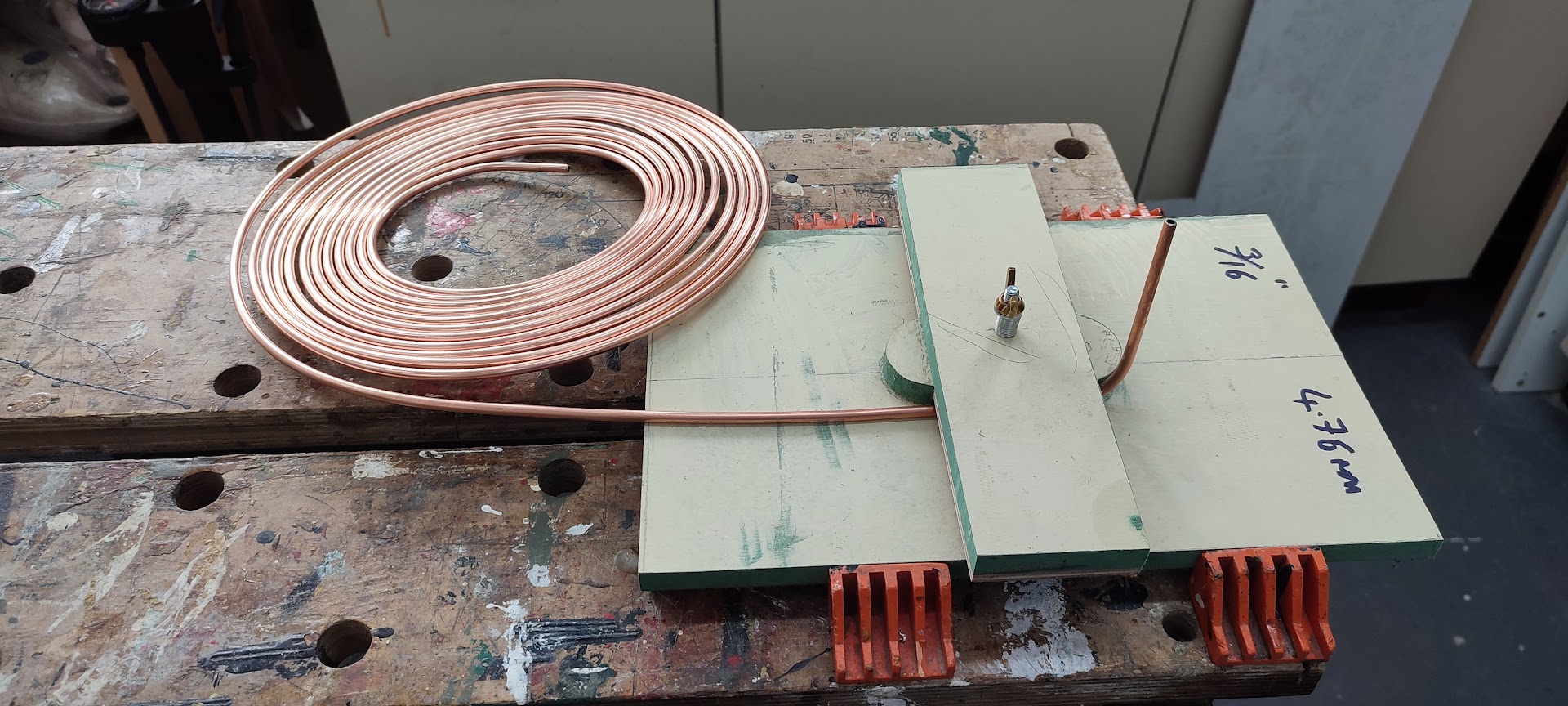
It was at this point that the failure to spot an error in the CAD drawing led subsequently to much extra work. The key point was that, with the sausage in place, the perimeter needs to be same width all the way around so that the pipe will fill the whole space. The measurement of the sausage given on the drawing was too large which meant that the perimeter at the ends was shorter than at the sides. It was only after about half a roll of 3/16” pipe had been laboriously wound around the jig that the error became obvious. The drawing of the jig shown here has been corrected so anybody following this procedure should avoid the mistake.
The coil then had to be unwound to a straight piece of pipe and then it had to be annealed with the blow lamp. While the metal was cooling some second thoughts were explored about how to use the jig. In the first attempt the jig was firmly fixed to the Workmate and the roll was carried around the jig as pipe was wound onto the coil. Now, with a 25ft tail that was no longer possible. The obvious answer seemed to be that the jig would need to rotate and the tail of pipe remain straight.
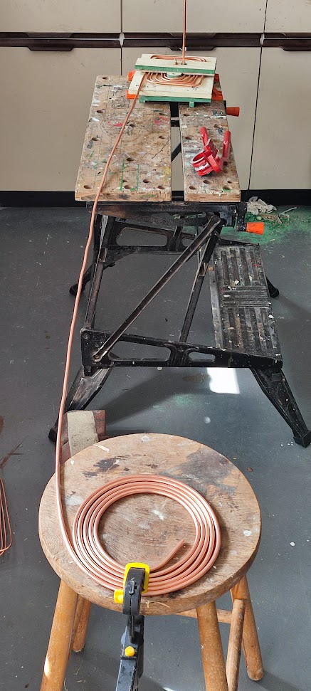 The central bolt that was designed to hold down the clamp piece on the larger jig was removed and the bolt on the smaller jig was given a lock nut on top. The bigger jig then fitted onto the bolt of the smaller jig and even when the clamp piece was screwed down it became possible to turn the jig. The 3/16” pipe when cooled was again fitted to the jig and the bending of corners and winding began again. The separate ‘bent’ 6mm spacer did work as the shaper for the corners but required some serious strength to get the pipes to take up the desired line. There was a tendency for the coil to try to become somewhat circular so the clamp piece needed removing after almost every corner to re-adjust the line of the pipe.
When it came to the ¼” pipe the same approach was applied but it was found that the pipe was significantly harder to bend. Thus after three or four circuits the developing coil was removed from the jig and the pipe bender applied. It was found that if the lined up pipe was nice and straight then that was captured in the coil. With a little care it was possible to estimate where the bender should be located to maintain the desired 6mm distance from the previous circuit. The developing coil was dropped back onto the jig every so often to ensure that it was close to the planned design.
Once the jig had been filled with pipe in the form of nine circuits care was taken to ensure that a straight piece of pipe came out to the ‘outside’. For the ¼” wind this was expected from the calculations to be about 560mm. However it turned out to rather more than this. The 3/16” pipe also had quite a long ‘tail’ but was closer to the expected amount. Thus the question arose of what to do with the ‘extra’ pipe.
It was decided that an extra coil layer would make sense and so the ¼” winding was turned over and the excess pipe bent into a square coil using the hand pipe bending tool. The first bend went badly and the pipe nearly collapsed instead of bending as it had done before. It was quickly annealed, straightened and hammered back to an approximation of round. The second attempt was done very carefully and a smooth curve was achieved. The rest of the corners worked satisfactorily. Winding stopped when there was a straight length long enough to come out of the short side of the jig. That will be either the point of connection to the 3/16” pipe or output to the water separator.
Next thought was given to how to connect the 3/16” coil to the ¼” coil. For somebody with good silver soldering technique the two ends would obviously be soldered. However, for those us with less skill in that area an alternative needed to be found. The simplest seemed to be to bring the pipes out of the heated area of the boiler and have a compression elbow at the end of each with a short length of pipe to connect the elbows. The pipe ends could all have solder cones and this would have the advantage of making the system easy to dismantle should the need arise.
With that ‘plan’ in mind the next step was to mount a pair of cross pieces to each coil to ensure that the pipe stayed where it should. After some thought it was decided that these items might as well be brass angle since I had some in my metals collection. Unfortunately, my memory proved to be faulty and the available angle was short in length and very thin. A quick exploration online soon yielded a supplier and a set of four lengths of Brass Angle 9.5mm x 9.5mm x 1.6mm Wall cut to 220mm were ordered.
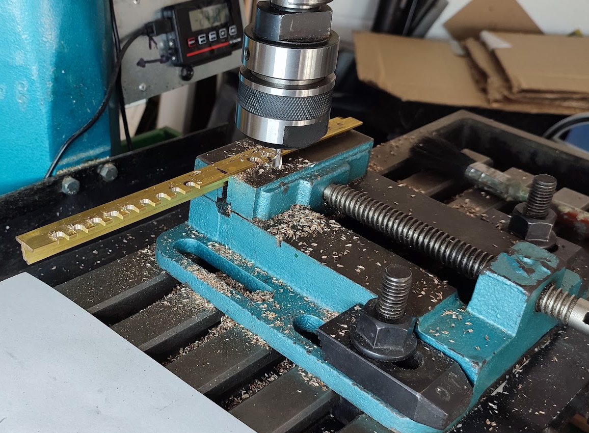 At the next stage, common sense slipped and I went back to the CAD drawings, did a few measurements and produced a table of slots to cut into the brass angle for the 3/16” coil. The brass angle was soon mounted in the mill and the slots were cut. Taking the bar to the winding it was instantly clear that the slots were in wrong place. Thus it was a case of getting out the laptop, doing some measurements of the actual coil and then producing a better cutting table. Whilst the individual differences for the new slots were small, over the whole width the change made it possible to haul the pipe into place in a sensible slot without too much effort. Naturally, the coil was sufficiently inaccurate that the pipe did not just drop into place. Copper wire was used to tie down each pipe into its slot. With the two bars fitted to the 3/16” coil the whole assembly became reasonably rigid.
Moving on to the ¼” coil, the cutting table for the angle bars was derived from the actual coil and a ¼” end mill purchased to do the work. For all this cutting the digital read out on the mill was essential as was the spreadsheet table. Doing mental arithmetic on the fly is good, but it is too easy to make mistakes or to forget the point one has reached.
Whilst the ¼” coil looked as if it was closer to the theoretical design, in practice it was found to be much more variable, especially for the central bends. With the pipe being thicker it was much more difficult to ‘adjust’ bends to make the pipe fit into the slots easily. This was eventually achieved by tying down the pipe one position at a time from the outside. The tie downs were short lengths of copper wire.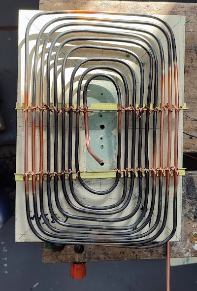
Given the amount of spring left in the ¼” pipe and the extra work on the 3/16” pipe it was clear that the two completed ‘packs’ of coils should be thoroughly annealed. Advice was receives that for cunifer pipe the annealing process must involve heating to red hot and then quenching in water. To make the heating process easier a new burner was sought for my MAP gas torch that had a wider flame. Even so the process looked as if it would take some time.
Finally, with the two packs of coils complete and annealed the next step will be to acquire the material for the casing and assemble that. With the casing complete it will then be possible to install the heating coils and move to setting up the pump, the water separator and the system controls. 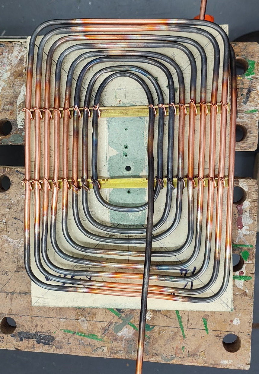 The next section will outline the building of the boiler casing.