Arranging the Coils
12th August 2023 - Arranging the Coils
If one looks at the various mono-tube designs that have been reported in Funnel and similar sources, one of the striking similarities is that the majority of coils are vertical. In that format the water is pumped in from the top with the steam exiting at the bottom. Westbury (1949) calls this the contraflow system. Usually associated with that layout is a further coil or similar in the funnel to pre-heat the feed water. All of this is to try to extract as much energy from the fire as possible.
By comparison Westbury (1949) reports that the majority of the racing model boat ‘flash’ boilers have the coil arranged horizontally*. However, the purpose of this configuration is to create a light weight, low profile boiler that will generate steam quickly and in considerable quantities but in which fuel efficiency is not necessarily a high priority.
With a vertical coil design the water is likely to turn to steam before it reaches the last circuit whose purpose is essentially to dry the steam. The point at which the water in the coil turns to steam is not generally known though Mounster (1986) hazarded a guess that for his system it was half way along the coil. It was on that assumption that he mounted a temperature sensor at the half way point and used it as a key variable in his control system. Similarly White (1997) cautioned that extending a coil beyond a certain length was unlikely to generate more steam but would certainly increase the temperature of the steam. This effect was recently confirmed by Robinson (2023 Private correspondence) who reported that extending the length of the coil in Taniwha had increased fuel efficiency but also led to much hotter steam.
In the previous section it was stated that the Snipe boiler design seemed to be the best fit for the Fairlight Project as it was wood fired, low in profile and successful in operation. That low profile was achieved by having the coil(s) in a horizontal position. Unfortunately, such a configuration makes it difficult for the contraflow system to be used. Thus the question arose as to whether it was possible to find a different coil configuration that would achieve the low profile of Snipe whilst possibly adopting the contraflow approach for improved energy efficiency.
Discussion with John Emmett, the designer of the Snipe boiler, led to the suggestion of a ‘chaos’ wind for the coil. This was modelled in wire and looked promising as it looked as if the contraflow design could be achieved.
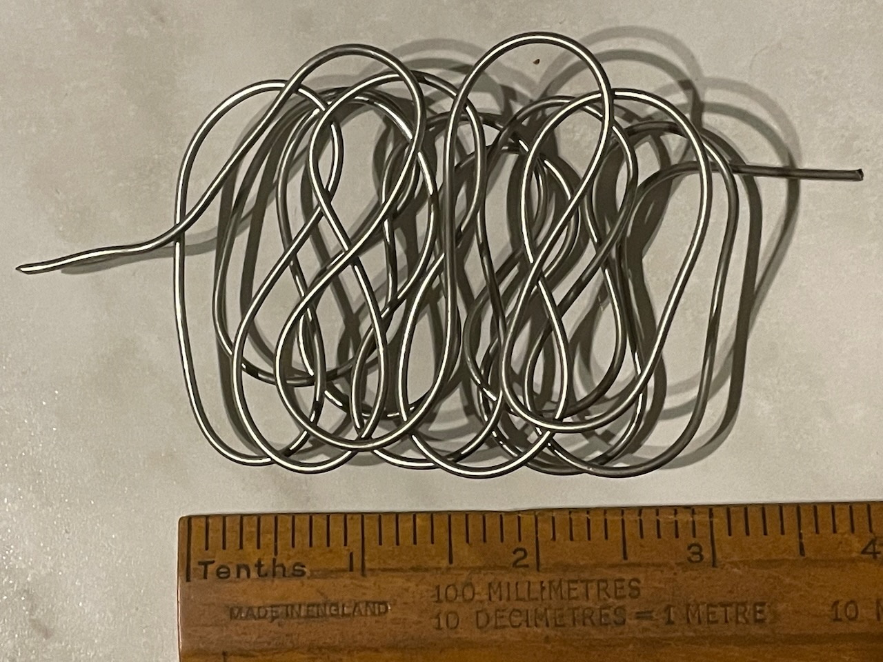
To move from the model to implementation in pipe, the idea was drawn in CAD. It was quickly realised that the nick name ‘chaos’ was perhaps inappropriate since the addition of specific bend radii applied to all bends turned the design into a regular pattern.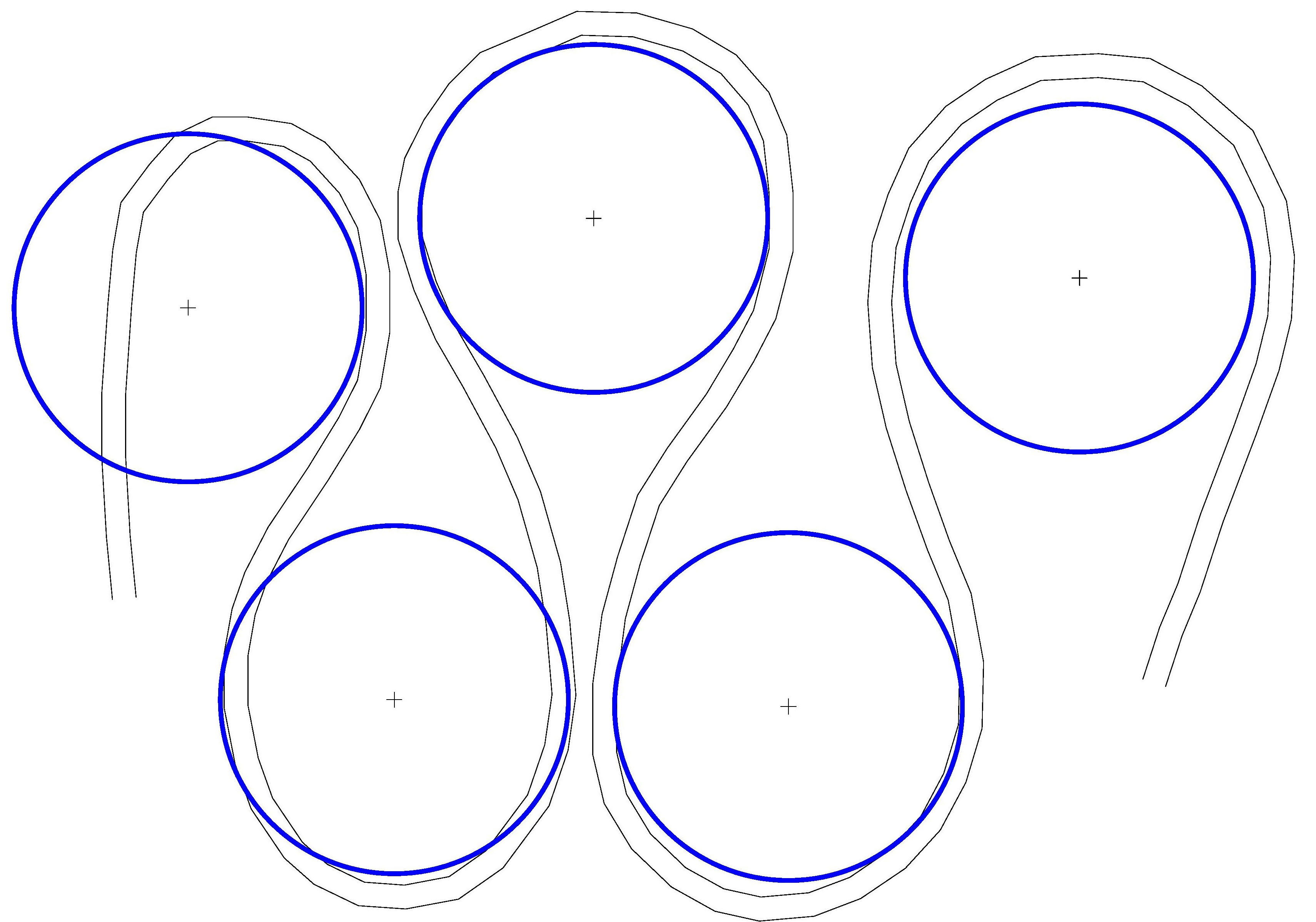
It was then re-drawn based upon the known minimum bending radii of 3/16” cunifer pipe. The resulting design looked promising and a further drawing was developed layering the pattern to see how much was ‘air space’ and how much ‘metal space’. That too looked promising so a pipe bending jig was created and a 25ft length of 3/16” pipe was processed.
The test showed that such a bending pattern was possible, although not easy to create. It also showed that the expected compactness of the layers was nearly impossible. There was clearly way too much air and not enough metal suggesting that a great deal of the heat from the fire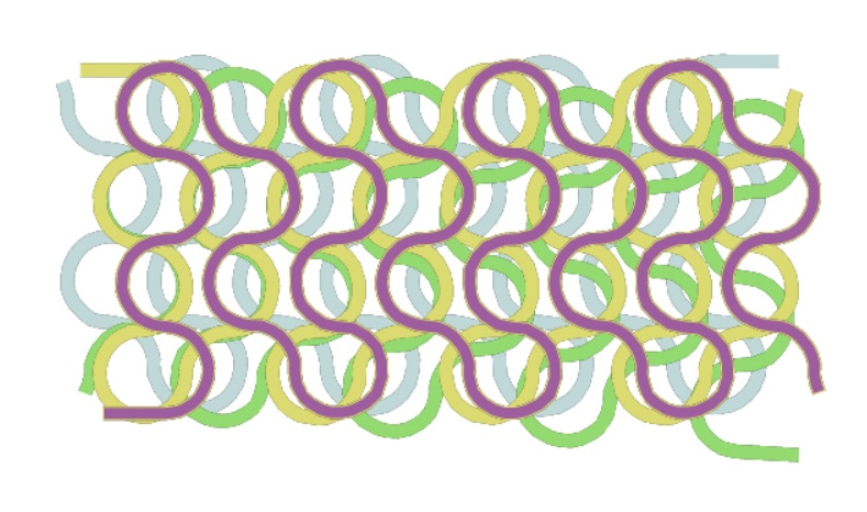 would disappear up the funnel without generating any steam.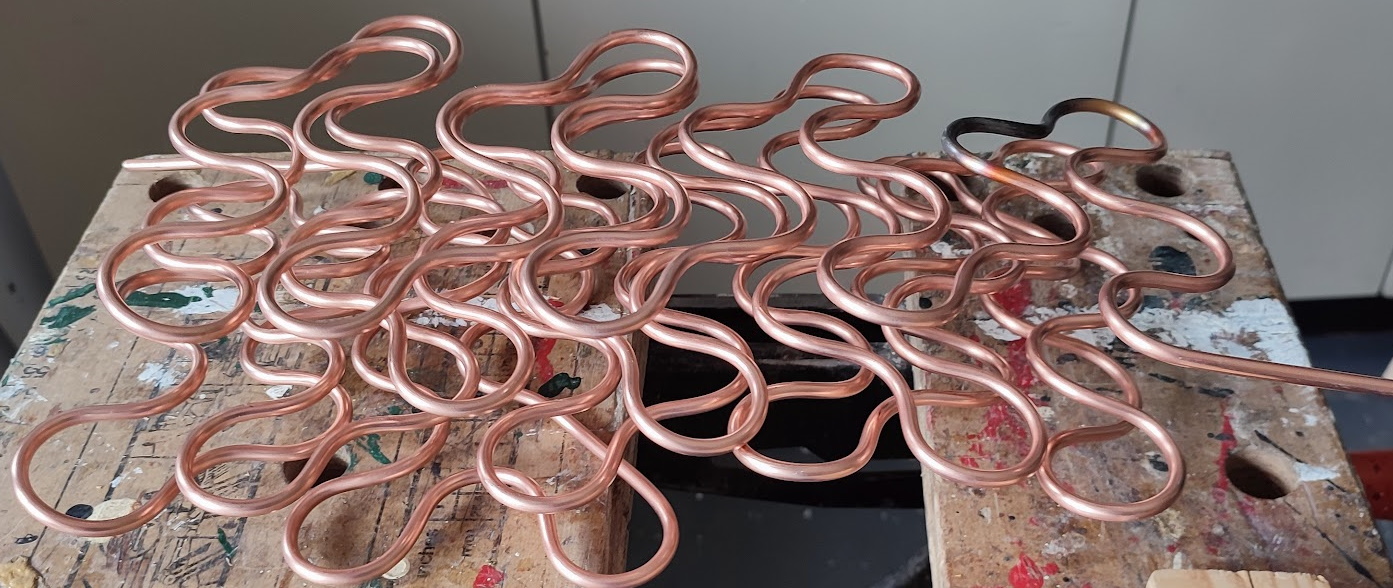
Further discussion led to the idea of a flat coil such as that used by Young (1985) except that the coil would be rectangular rather than circular as in Young’s design. It was felt that the flat coil would present much more metal to the combustion gasses and it would be much easier to get several layers in a small space.
For both the first test design and the flat coil design it was expected that the heated element would be two or three flat coils with a rectangular outline since the boiler casing is rectangular. Given that the top of the boiler casing is rounded the top layer would be smaller than the lower layers. Approximate positions for the layers were estimated and the ‘boundaries’ measured.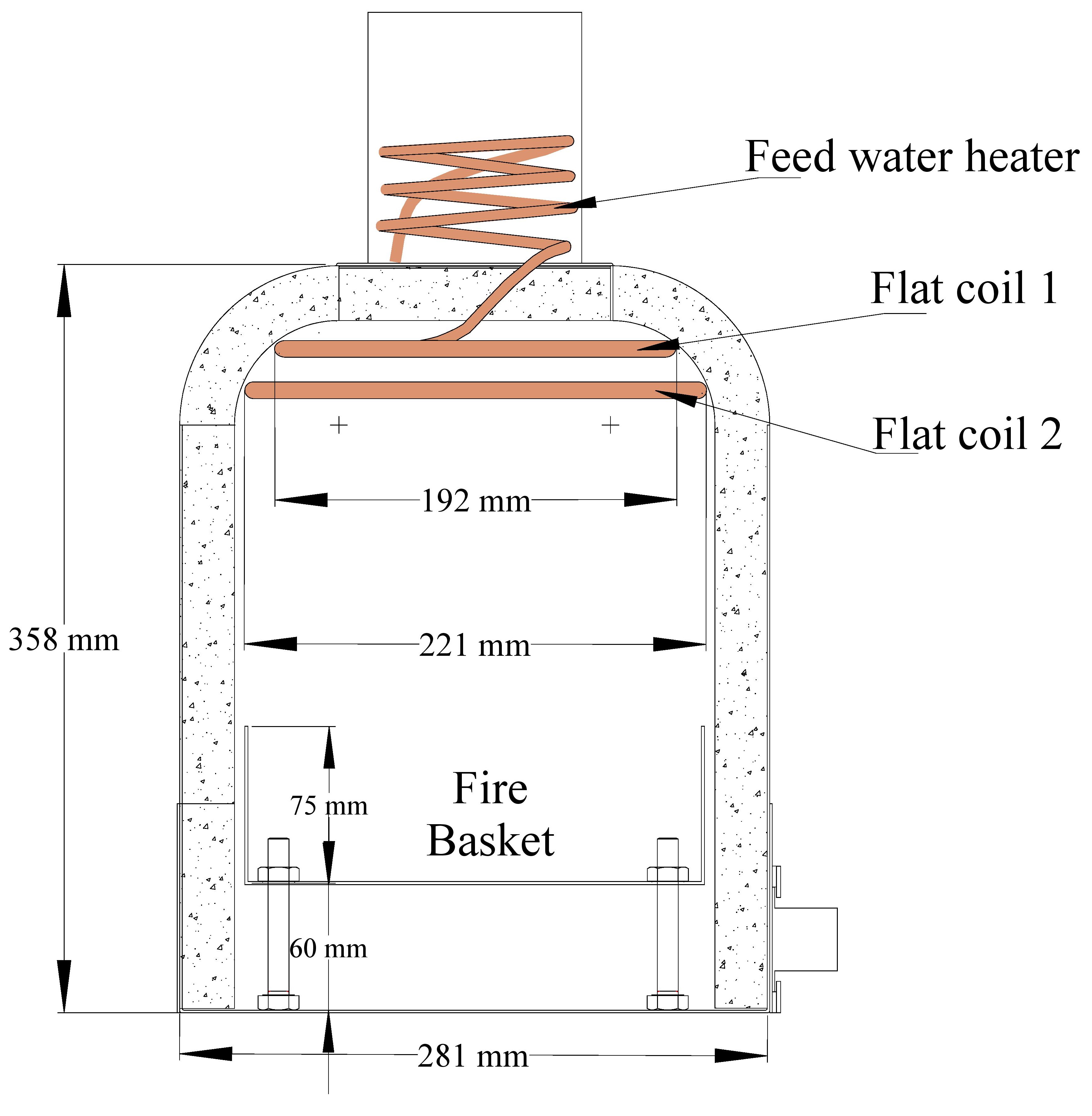
One advantage of the ‘traditional’ circular coil is that it can usually be wound quite quickly if a former of the correct diameter is available. However, winding a rectangle posed a number of problems. The first was to design a former or jig that would put the bends in the right place and with the right radius bends. The second issue was to assess just how much pipe the design would swallow. It looked from previous articles as if the length of the pipe was established first, it was then wound and finally the diameter of the casing was established. For this boiler the size of the rectangle has been established first and then the pipe applied to it. Clearly this is where CAD saves much work and can give answers relatively quickly. Of course, as can be seen in the diagram below, the answers are not necessarily the ones that one might have wished to receive. For all three pipe size possibilities drawn this rectangular coil does not neatly swallow the standard 25ft coil of cunifer pipe.
Given that 50ft, comprising two of the readily available standard lengths of cunifer pipe, has been successful for the vessels examined in the earlier table it seemed sensible to take that length as the target. The material to hand consisted of one unused 25ft coil of 3/16”, one coil of ¼” and one coil of 5/16” with two test bends in it. Since the ID of 5/16” pipe is 6.52 mm while the OD of ¼” pipe is 6.35 mm the opportunity to easily make a silver solder join is available. The same is true of ¼” and 3/16” pipe with the latter having an ID of 4.93mm while the 3/16” is 4.76 mm OD. Thus 3/16” and ¼” paired or ¼” and 5/16” paired would also work.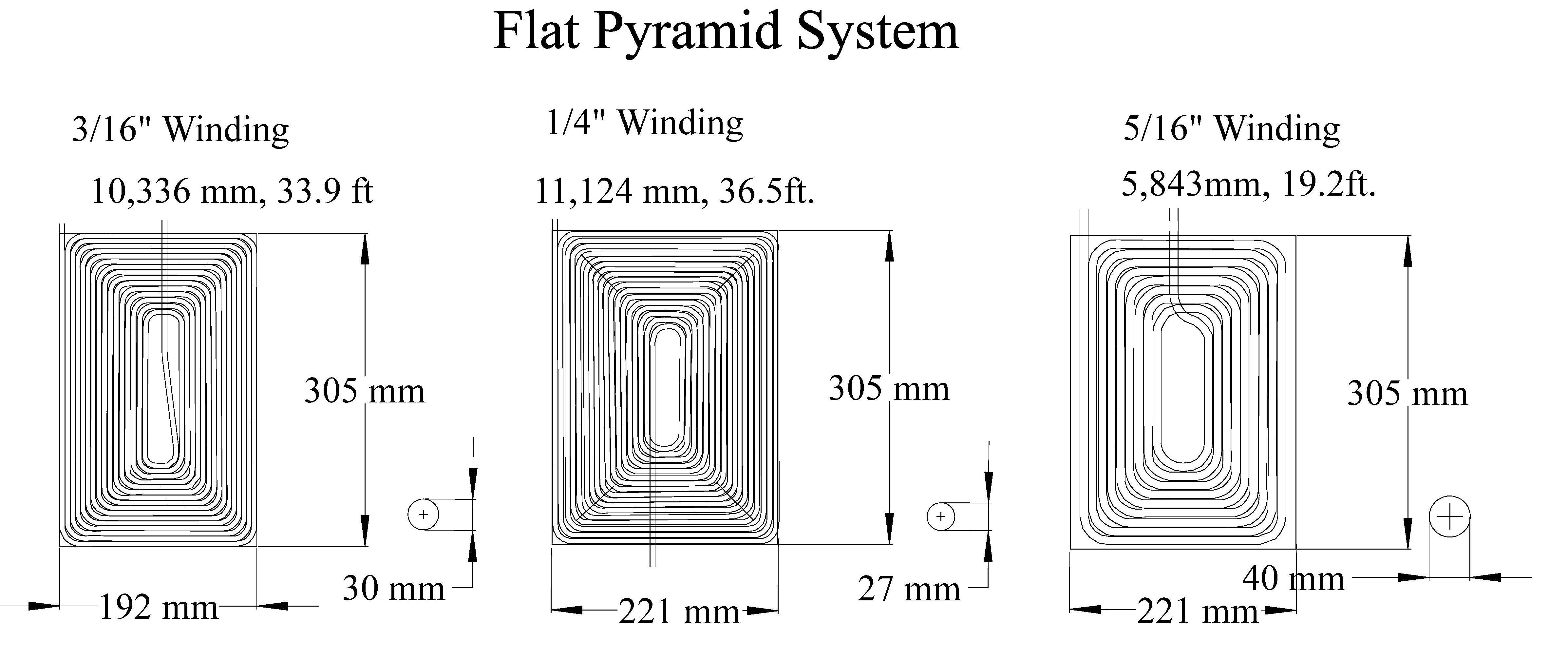
The 5/16” coil and the ¼” coil together come to just over 50 ft (55.7ft) in the drawing but given the evidence presented by White (1997) the more effective pairing might be 3/16” and ¼”. However, those two drawings amount to 70.4 ft whereas the two available physical coils only amount to 50ft. This is, perhaps, an appropriate opportunity to raise a question about the coils particularly in relation to the relationship between metal and air.
In the discussion of the design of Snipe’s boiler it was pointed out that “burning one gram of fuel per second (3.6kg per hour), 14 litres of air must also pass through the boiler every second. Thus a clear ash pan inlet passage of 140 sq cm will force the cold air to flow at a metre per second. In order to keep acceleration to the minimum therefore, cross sections of 700 sq cm in the firebox and 280 sq cm at the funnel will be needed. This yields approximately 7 inches as the internal funnel diameter. A metre per second may be an ambitious target, but 4 metres per second is definitely too much to expect for natural draft.” (Cuthbert & Emmett 2023)
Taking the target of 280 sq. cm. which is the required flue area, one would expect that the rectangular coils would contain 280 sq cm (28,000 sq mm) of air gap. Taking the 3/16” winding, the space in which the winding fits is (192 X 305) = 586 sq cm. The 3/16” tube is 4.76 mm wide and 10,336mm (33.9 ft) long which amounts to 492 sq cm. Thus the air gap in this design is (586 – 492) = 94 sq cm which is around 1/3 of the desired space. The conclusion must be that the design as shown is too ‘tightly’ drawn and needs to be reworked. However one must not forget that a ‘standard’ coil is 25ft long so the calculation above is into ‘theoretical’ territory using a longer pipe than is available.
To get some clarity a little time was spent creating a worksheet in which the key variables could be entered and the outcomes explored. Inputs were the length and breadth of the casing at the proposed position of the coil, the outside diameter of the pipe, the minimum bend radius of the pipe, and the gap between the circuits of pipe. This tool reported the length of the pipe after each circuit had been wound. An additional calculation gave the area of the casing and the area of metal for the chosen pipe size assuming that the 25ft cunifer coil was the available material.
For the 3/16” tube it was found that the 25ft length would comprise 10 coils using a 6mm gap and that would yield a theoretical air space of 230 sq cm or 39% of the casing area. For the ¼” tube it was found that using a 25ft length of cunifer and a 6mm gap between the tubes gives a theoretical air space of 226 sq cm which is 33% of the casing area.
The useful point that emerged from this exploration is that the heating coils would comprise just two layers that would use up the majority of the material in a ‘standard’ roll of cunifer. With that established the next obvious step was to work out how the pipe would be bent to the desired shape. The experiment with the ‘Chaos’ trial showed that the 3/16” pipe bends quite well without the need for a bending tool. The 5/16” material was much stiffer and required the use of the pipe bender but the hope is that the ¼” material is only slightly stiffer than the 3/16” material.
On that assumption a bending former/jig was designed assuming that the coil would start at the centre. The two parameters that define the starting point are the fact that the coil will be rectangular and that the specified bending radius would be 20mm. While 3/16” pipe can 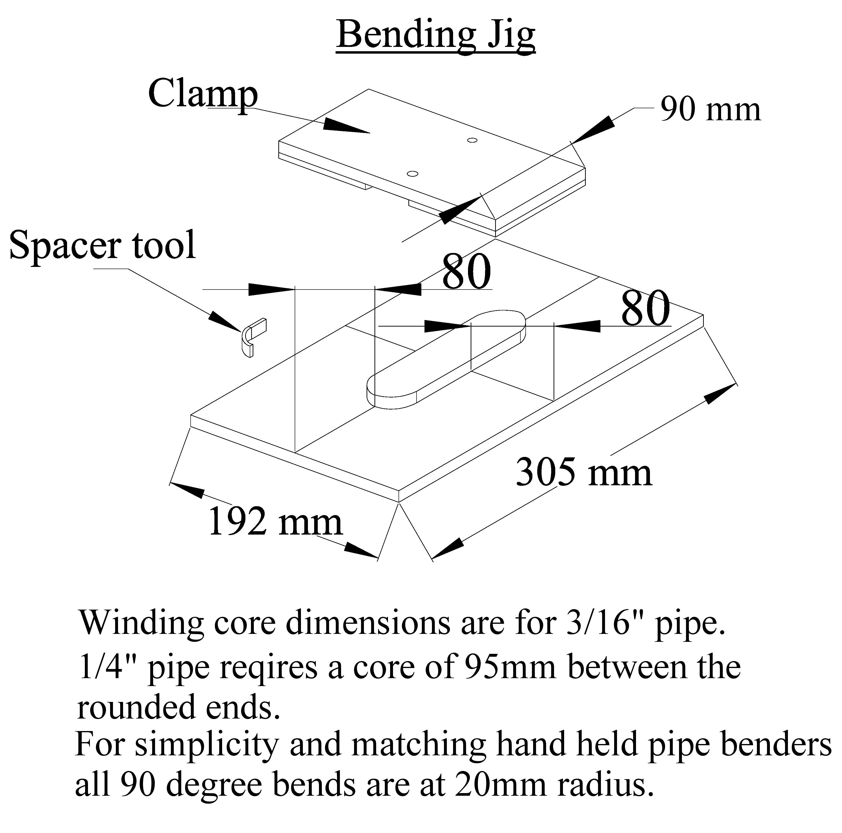 be bent to a smaller radius, it seemed sensible to use the value that matches the available pipe bending tool in case its services were required. Thus the starting core is a sausage shaped former made of 10mm MDF that is 40mm wide. The rounded ends of this core piece are at 20mm radius which is the standard set for all bends in this exercise. The use of MDF is simply down to the fact that there is a significant amount of it in the ‘might come in useful later’ store. Keeping the coils of pipe apart when bending seemed to be best done by inserting a 6mm curved spacer. A number of other straight spacers will be required in order to keep the coil in shape elsewhere.
The diagram shows measurements of 80mm for the ends and sides of the base. This is the calculated width of nine circuits of pipe plus spacing plus a little extra. In setting the base board up it is important to make sure these two dimensions are the same by adjusting the length of the 'sausage' spacer in the middle. In my first attempt I made a mistake in the measurement which only became evident half way through the first bending exercise.
It has also been decided that the first bend will be upwards to provide a short length to connect the feed water pre-heating coil in the chimney stub. Being clear of the fire it is assumed that this connection can be made with a compression joint and solder cones.
The next section of this discussion will report on the experience of creating the two rectangular coils.
References
Cuthbert P. & Emmett J. (2023) The Mono-tube Steam Generator Part 1 – History and thoughts for launch use, Funnel Issue 195, Winter 2022, p.63.
Mounster W. (1986) Development of a modern steamboat – Part 1 – A mono-tube boiler. Funnel Issue 48, Summer, p. 40.
Westbury ET (1949) Flash Steam, TEE Publishing, Leamington Spa.
White J. (1997) The development of a Small Mono-tube Steam Generator, Funnel, Issue 92, Spring p. 36.
Young G B (1985) A mono-tube boiler. Funnel, Issue 45, Autumn, p. 35.
(*None of the designs shown by Westbury are actually Flash boilers where water is sent to an already hot coil. They all appear to be varieties of the mono-tube type.)