30th July 2026 - Gathering the loose ends
With the batteries delivered and associated fittings delivered it seemed sensible to try to bring together the various bits that were in the garage workshop or on the study desk. A first step was to report back to Deep Seek and seek advice on swapping the 30 Amp fuses for something a little lower. There was also the question of how to actually get the computer controlling the plant. At that point the computer was set up to collect two lots of temperature data and, following 'nagging' from Deep Seek the manifold pressure. The only control feature on the table was the switchable PWM box for controlling the pump that required the skipper to do the switching. Thus the system so far was basically a data collection system not a control system.
There followed a discussion about controlling the feed water. The aim was always that there should be a closed circuit system based around the hot well. The pump would take water from the hot well and send it in the direction of the heating coil with the volume dependent upon the PWM setting. The missing component was the valve in the circuit, controlled by the computer, which would bleed off some of that water back to the hot well. With that in place there was not only data collection but control. The other issue that had been ignored was the damper. As originally designed when the case was drawn up, it was simply four holes with a sliding cover. If the system was to be under computer control it would also make sense for that slider to be operated by the computer.
Deep Seek agreed that these changes were essential and also pressed me to add in a third thermocouple that had been discovered in the garage which would measure the temperature of the flue gas as a surrogate for the fire. Originally it had been though that a domestic wood stove thermometer would be sufficient, but Deep Seek disagreed. That the fire would be managed by the skipper was also another potential point of contention as a liquid fuelled fire would have allowed the use of a computer controlled fuel flow.
With a direction of travel set up it was time to get back into the garage. The manifold was carefully removed from the casing and, with careful measurements, mounted in the milling machine vice. It was found that there was just sufficient space on the back of the manifold to drill and tap another port. With a pair of elbows that would allow the pressure sensor to be fitted as high as possible and generally out of the way.
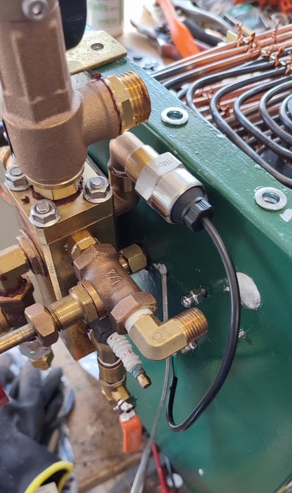 |
The plan worked and the sensor was soon mounted on the rear of the manifold. There was an urge to screw the manifold back into place but the steam outlet from the coil had not been connected previously. Additionally, the second thermocouple needed to be secured as close to the end of the coil as possible and a 'way out' to be found for the cable.
With that achieved, it then became possible to look for somewhere to fit the third thermocouple to monitor the flue gas. That turned out to be much less of a problem than expected. There is a hole leading to the funnel through the insulation protection sheet on the casing top panel.
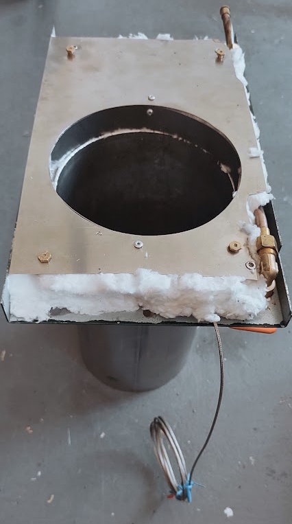 |
To keep the fire gas going to the funnel and to avoid the insulation getting chocked with soot a ring of stainless steel sheet had been fitted. It seemed obvious that the ring was the ideal location to rivet the active end of the thermocouple and the cable could disappear out of the casing on the 'cold' side of the insulation.
With that sorted it became possible to connect the steam pipe to the manifold and then secure the manifold to the casing. Finally, the four supporting rods that hold the coil in place were re-fitted and the whole assembly became reasonably rigid. Of course at that point it was remembered that fixing the top panel to the end panels of the casing with nuts an bolts was less than satisfactory as the nuts were almost impossible to attach to the bolts never mind mounting a spanner. That problem had been identified some time before and a set of stainless Rivnuts acquired. The first one was set into the now enlarged hole and the Rivnut compression tool was applied. Two handed squeezing of the tool produced zero results. Stainless Rivnuts are tough! The way around was a set of M6 washers, a 50mm M6 bolt, and M6 plain nut, the adjustable spanner and the heavy duty socket set. With that set up it was possible, albeit with some effort, to get the Rivnuts squeezed and locked into place.
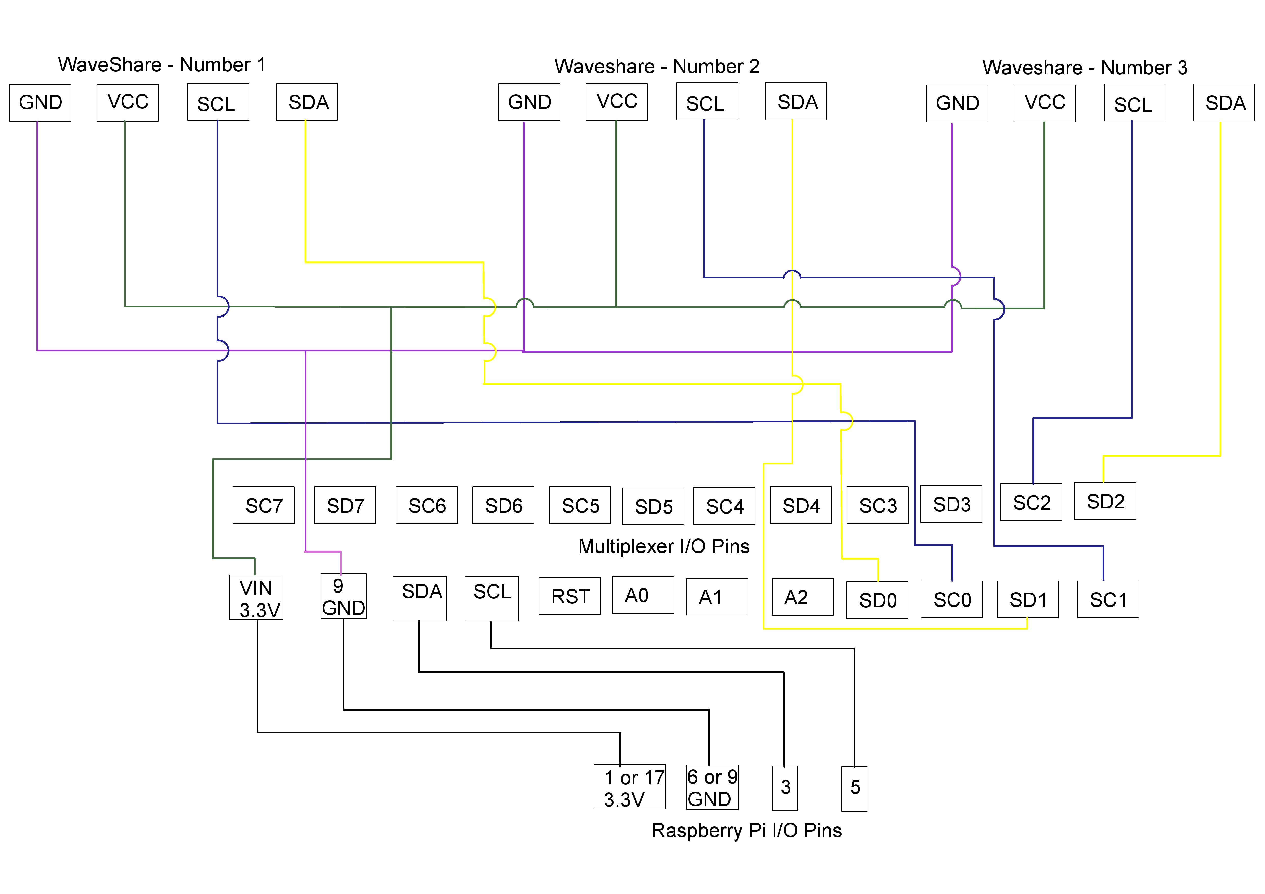
Meanwhile, back in the Study some of the 'little bags of electronic goodies' had arrived. The third Waveshare screen arrived and was soon connected in with the others thanks to the flexibility of the Wago Clips. The connection to the Miltiplexer was held over until there was time for a round up with Deep Seek. The third MAX6675 board was similarly partially wired ready for the final wiring conversation. In the meantime the analogue-digital converter board had arrived for the pressure sensor but before it could be connected it need a row of header pins soldering on.
With that little soldering job done it seemed sensible to recover the wiring diagram for the WaveShare screens and the multiplexer and edit it to include the third screen. It took a little while to get a picture that looked like a sensible wiring diagram and not knitting and the result is below:
 |
With that done the actual wiring was completed and the Raspberry Pi fired up. The existing Python program was set up for just two sensors and two screens so it seemed sensible to open Thonny, the program editor, and begin the edit. Much time and effort was put into the task, but that was no substitute for a good knowledge of Python. It seemed sensible to stop and ask Deep Seek to correct the errors. For some unknown reason, Deep Seek was not available so an alternative solution was needed. Fortunately, an article written by a young relative who is a well thought of programmer and system designer, had recommended Claude AI as the best programmer's productivity enhancement tool. Signing up to Claude was simple, the issue was explained and, using Tiger VNC to copy the program text to the PC, the erroneous program was submitted. Very quickly a list of suggested corrections was supplied but also a brand new program. Claude explained that a few improvements had been added such as avoiding the screen flicker that the old program had induced. The program was quickly copied back to the Pi and tested. It worked first time and displayed reading from the three thermocouples.