With the drawings of the casing completed and despatched to potential material suppliers the next stage in the process would seem to be some design work on the ‘plumbing’ of the boiler. The internal plumbing was sketched out earlier but that which mostly resides outside the boiler has not been designed.
The first element is quite simple as the outlet from the heating coil will be carried across to the manifold. That will be the distribution centre from which steam and condensate will be piped to useful tasks.
The principal component on the manifold will be the safety valve which will need to have its outlet plumbed to the back of the funnel if traditional layout is to be adopted. Given the data that has been accumulated about other steam canoes a target pressure of 90 PSI (6 bar) would seem reasonable at which pressure saturated steam is rated at just over 166degrees C. Thus the safety valve should have a temperature range of up to (say) 180 degrees C. Its input diameter should be larger than ¼” which is the size of the steam supply pipe so 3/8” BSP would probably do. The volume of steam that the boiler could produce has not been calculated yet, but the throughput of the valve must exceed that if it is to do its job. That at least should be sufficient detail to facilitate the finding of a suitable device from steam equipment suppliers.
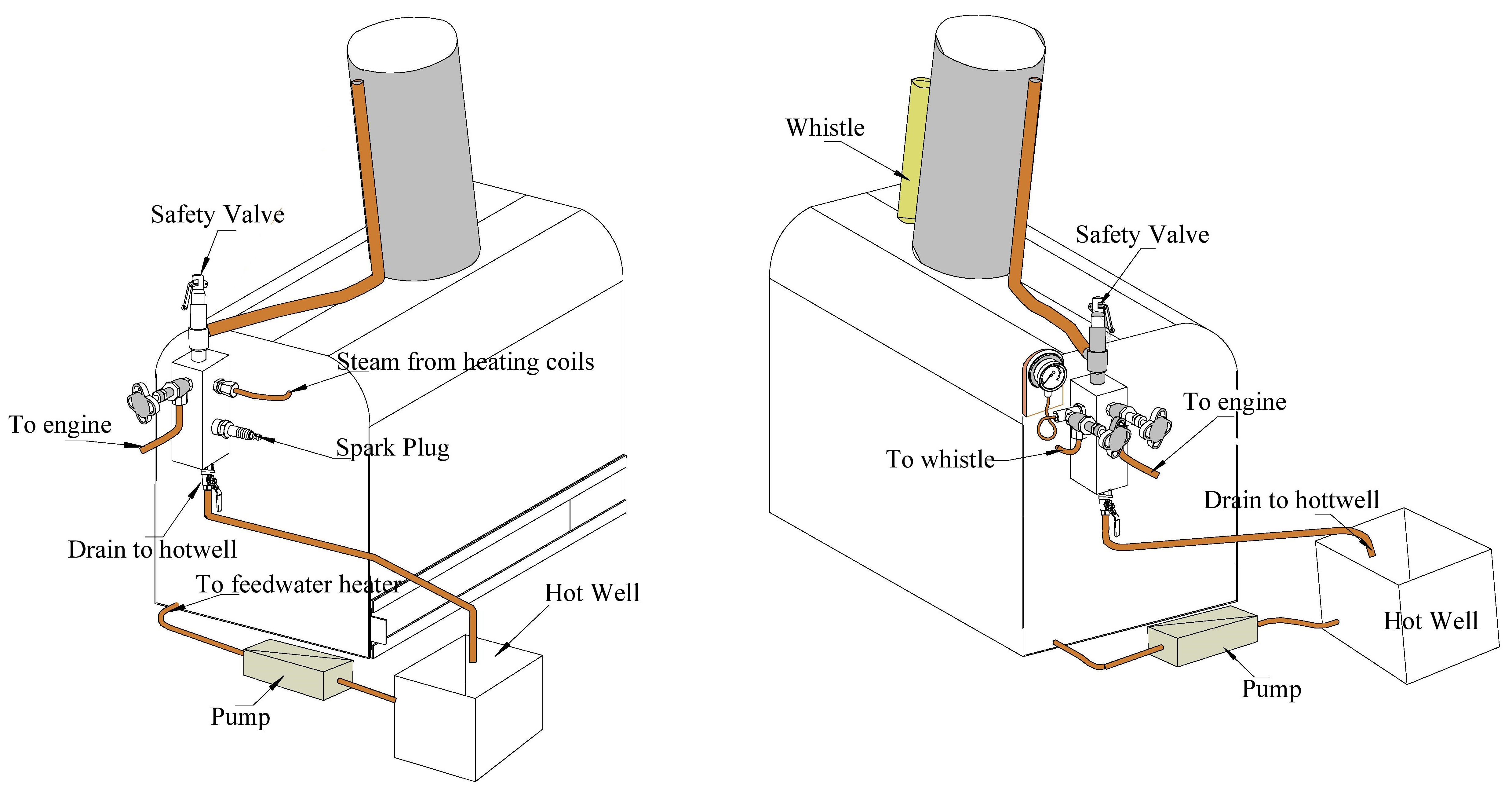
The next major item is the valve that controls the supply of steam to the engine. In conventional boilers this is the valve that is used to regulate engine speed. However in the mono-tube and engine combination the speed of the engine is mostly regulated by the size of the fire so this valve, whilst necessary, will not get a great deal of use. If the engine needs to be stopped whilst the fire is still active two steps need to be taken. On the one hand the steam valve needs to be closed and on the other the drain valve to the hot well needs to be opened. The latter will simply vent steam into the hot well since shutting down a mono-tube temporarily is not that easy.
Another important, but possibly surprising element in the manifold is the mini spark plug. Its role in this context is not to create a spark but to act as a switch for a low power current. While the manifold is full of steam no current will flow. However, when the bottom of the manifold fills with condensed water it will ‘short circuit’ the spark plug which in turn will light up a warning light and/or sound a buzzer to let the skipper know that the manifold drain needs to be opened.
Whilst much of the instrumentation for this boiler will be electronic, there is also a place for a traditional pressure gauge. If a tee is fitted to the other side of the manifold a suitable small bore pipe can be arranged to give the necessary ‘U’ bend to the gauge. Given the limited space on the rear of the boiler casing it would seem likely that the gauge would be mounted on a suitable board.
The tee for the gauge can also support the supply to the whistle. It is proposed that the whistle should be an ‘organ pipe’ style whistle which implies a fairly long, slim body and a rather deeper note than is produced by short whistles. This would be mounted on a bracket on the casing in front of the funnel. The reason for this is that whistles can blow out a fair bit of hot water as they start and that is best kept away from the skipper. It also means that the sound is not blanketed by the funnel. With a socket fitting on top of the casing it will be easy to remove the whistle when the boiler is to be removed from the boat. The supply will also be inside the boiler casing and so will keep hot which ought to reduce the amount of condensation that gathers in the supply pipe. Using a conventional valve seems the best option as small whistle valves can be rather unreliable and the traditional type would require a cord or rod to operate it.
The other possible auxiliary item is a blower that can be used to draw the fire. Since the design has a fairly large and long funnel it is likely that a blower will not really be necessary. A number of the steam canoes whose data has been examined have been ‘puffers’ in which the water in which the boat floats provides the boiler feed and for which the exhaust steam is vented up the funnel to ‘encourage’ the fire. The likely waters in which the Fairlight might be used are completely unsuitable as feed water and thus a condenser and hot well system is proposed. The advantage of this is that is a semi-closed system in which high quality water can be used and the possibility of scale developing in the mono-tube can be eliminated.
With a general overview of the external plumbing now available, the next task is to identify and obtain the necessary commercially produced components such as the valves, and plumbing connections. Once the casing components have been received from the suppliers, the next stage after that will be to bring together all the parts and assemble the hardware.